![Sabanto-Horizontal-Orange-on-Transparent-RGB-1080px-05.16.23.png]](https://support.sabantoag.com/hs-fs/hubfs/Sabanto-Horizontal-Orange-on-Transparent-RGB-1080px-05.16.23.png?height=50&name=Sabanto-Horizontal-Orange-on-Transparent-RGB-1080px-05.16.23.png)
Introduction
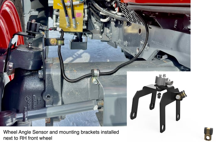
This chapter describes how to install the Wheel Angle Sensor (W.A.S.) components onto the front axle of a Kubota M5 4WD tractor. The sensor body and potentiometer shaft are attached to two separate brackets that are connected to the wheel knuckle and front axle in order to sense the angle of the front-RH wheel.
Sensor Alignment is Critical for Durability
In order to ensure that the pivot of the steering knuckle does not cause the sensor shaft to bind or shear during steering rotation, Sabanto provides a specialized alignment tool that is used during installation of the inner and outer WAS brackets. This tool ensures that the axis of rotation of the sensor precisely aligns with the axis of the steering motion of the tractor, and thus its use is required during the sensor installation.
|
Alignment tool components
|

Alignment tool provides proper positioning of the inner and outer sensor brackets |

Wheel Angle Sensor Components

Special Tools Required
- Torque wrenches that can accommodate torques:
- as low as 2.5±0.5 N-m (22.1 in-lbs)
- up to 304 N-m (224 ft-lbs)
- Metric and Imperial sockets, box and hex-head wrenches
- M22, M24 wrenches
- M4, M5 hex-head wrenches
Installation
1. Wipe dirt from the top surface of RH front axle case support and remove the grease zerk, then insert the lower W.A.S. tool into the front axle case support. Gently thread the Lower W.A.S. tool.

2. Axle Disassembly
| Using M22 and M24 sockets/wrenches, remove the (4) M16 bolts from the front axle case support and the front axle case. These will be reused. | 
|
|
Although not necessary, should the need arise to raise the front axle while these M16 bolts are removed:
|
|

3. Secure the upper W.A.S. alignment tool to the outer W.A.S. support bracket

4. Sub-assemble the brackets and upper W.A.S. tool per the notes below:

5. Re-using the original M16 bolts, loosely attach the tool and bracket subassembly to the front axle as shown.
- Be sure to place (2) M16 flat washers between the outer W.A.S. bracket and the front axle case support.
- Insert the M5 x 40mm bolt into the center hole of the alignment tool.
- The M5 bolt will pass through the upper alignment tool and thread into the lower alignment tool.
- If a gap is present between the lower and upper W.A.S. tools, insert 1-3 M5 flat washers between the two tools to prevent deformation of the steering angle brackets. If no gap is present between the two tools, no shims are needed.
- Snug up the M5 x 40mm bolt.
6. Bolt Tightening Sequence

7. Begin removing the W.A.S alignment upper & lower tools, and hardware from the brackets.

| After the upper W.A.S. alignment tool is removed from the brackets, the distance between the top of the two bracket surfaces (shown to the right) should be 13mm. |  |
| IMPORTANT: To address any spring back, re-install the two M6 screws and three M5 screws in the alignment tool. Then loosen up the M16 bolts securing the outer WAS bracket and slide bracket upwards. Repeat steps 5-6 until no spring back occurs. | |
8. Loosely assemble the wheel angle sensor to the brackets. (Picture below)
9. Gently torque the M5 and M6 hardware to the values shown in the following picture.
- With the tractor’s engine running and the park brake set, gently turn the steering wheel full left and full right. Make sure the sensor does not bind up.
10. With the M5 & M6 hardware secured, Carefully tighten M16 bolts to approx. 200 ft-lbs (~270 N-m).
|
IMPORTANT:
|

11. Grease Zerk Installation

12. Plug harness into W.A.S. and secure harness branch
