![Sabanto-Horizontal-Orange-on-Transparent-RGB-1080px-05.16.23.png]](https://support.sabantoag.com/hs-fs/hubfs/Sabanto-Horizontal-Orange-on-Transparent-RGB-1080px-05.16.23.png?height=50&name=Sabanto-Horizontal-Orange-on-Transparent-RGB-1080px-05.16.23.png)
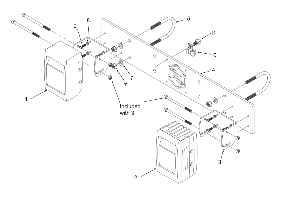
Parts list
|
ITEM |
QTY |
PART NUMBER |
DESCRIPTION |
|
1 |
1 |
9999-DD-1005A |
IR Illumination Unit |
|
2 |
1 |
9999-DD-1006A |
3D Sensor for Mobile Applications |
|
3 |
2 |
9999-HA-3002A |
U-Shaped Bracket |
|
4 |
1 |
0102-MP-1004A |
IFM Support Plate |
|
5 |
2 |
9999-HA-1042A |
U-Bolt, 5/16-18, 2” Inner Width |
|
6 |
4 |
9999-HA-1043A |
5/16 Washer |
|
7 |
4 |
9999-HA-1044A |
Serrated Flange Locknut, 5/16-18 |
|
8 |
8 |
9999-HA-1004A |
Split Lock Washer for M5 Screw |
|
9 |
8 |
9999-HA-1008A |
M5 Hex Head Screw, 16mm |
|
10 |
1 |
9999-HA-1023A |
Vibration-Damping Loop Clamp – ¼ ID |
|
11 |
1 |
9999-HA-1045A |
Flanged Hex Head Screw, 16mm |
|
12 |
1 |
9999-EH-3003 |
Obstacle Detection harness |
|
13 |
1 |
9999-EH-2002 |
MCI Cord 1m Sensor and Illumination |
Install Obstacle Detection
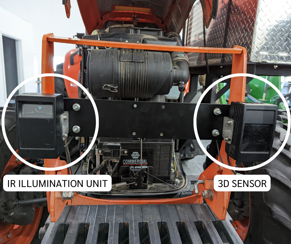
Before installation, ensure the vehicle is on a flat surface.
When facing the front of the tractor, mount the IR Illumination Unit on the left side, and the 3D Sensor on the right side.
Step 1
Attach the sensors to the IFM Support Plate:
- Locate the IR Illumination Unit and one U-Shaped Bracket.
- Attach the U-Shaped Bracket to the IFM Support Plate with 4x M5 Hex Head Screw - 16mm and 4x Split Lock Washer for M5 Screw on the left side of the IFM Support Plate.
- Attach the IR Illumination Unit to the U-Shaped Bracket with the M6 x 100 mm socket cap screws and locking nuts.
- Repeat substeps 1-4 with the 3D Sensor on the right side of the IFM Support Plate.
Step 2
Install the assembled IFM Support Plate to the front of the tractor using the supplied U-Bolts and hardware.
Step 3
Plug the MCI Connection Patch Cord into both of the sensors, The port is circled below.
Step 4
Adjusting your sensor angle:
Due to bracket tolerances, tire size, and other environmental factors it is highly un-advisable to use the degree increments provided on the U-Bracket as those measurements are most likely not accurate.
After tightening down your sensor, double check the angle, as the tightening sequence can tweak the angle.
- With your vehicle on a flat surface, zero out a digital angle finder to that flat surface
- Adjust the 3D sensor until it is angled straight forward at 0 degrees. Ensure your angle finder is on the back side of the sensor on the fins to ensure an accurate measurement.
- Tighten down the 3D Sensor, and ensure your angle has not changed.

4. With your vehicle on a flat surface, zero out a digital angle finder to that flat surface
5. Adjust the IR illumination until it is angled straight forward at 0 degrees. Ensure your angle finder is on the back side of the sensor to ensure an accurate measurement.
6. Tighten down the IR illumination unit, and ensure your angle has not changed.
Measuring the angle on the front of the sensor will provide inaccurate measurements
The center of the sensor has a ridge, placing your angle finder on this ridge will produce inaccurate measurements

Step 5
Attaching the obstacle detection harness to each camera:
Important: Plugging the obstacle detection harness into the wrong connectors will cause immediate damage to the cameras. The 15 amp fuse in the switch box harness may blow if the cameras are hooked up backwards and get powered on.
- Plug the m12 black connector on the obstacle detection harness into back of the IR Illumination Unit.
- Plug the m12 orange connector obstacle detection harness into the bottom of the 3D Sensor.

Step 6
Plug the Obstacle Detection camera harness 6-pin connector into the main vehicle wiring harness.
Step 7
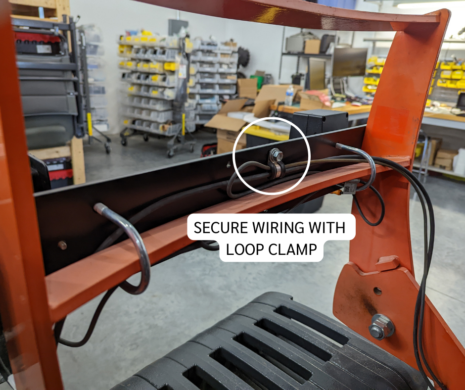
Secure the wiring:
- Attach one end of the Vibration-Damping Loop Clamp into the IFM Support Plate where shown.
- Run the wiring harnesses through the clamp, and then secure the second end of the clamp in place.