![Sabanto-Horizontal-Orange-on-Transparent-RGB-1080px-05.16.23.png]](https://support.sabantoag.com/hs-fs/hubfs/Sabanto-Horizontal-Orange-on-Transparent-RGB-1080px-05.16.23.png?height=50&name=Sabanto-Horizontal-Orange-on-Transparent-RGB-1080px-05.16.23.png)
Quick Search
Tools Needed
Camera measurement reference surface
Tightening order
Front Camera
Rear Camera
Left Camera
Right Camera
Tools Needed
- Digital angle cube
- Digital angle finder protractor
- Assorted wrenches / sockets to tighten camera bolts
- Philips screwdriver
- Flat concrete surface
Camera measurement reference surface
Not using the cameras top face as a reference surface for measuring roll and pitch can result in improper calibration.
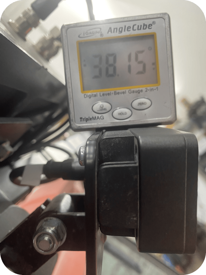
In the left photo below, the angle finder is placed on the rear fins of the camera, along with the bracket it is attached to. This positioning causes the angle gauge to tilt backward, leading to inaccurate measurements.
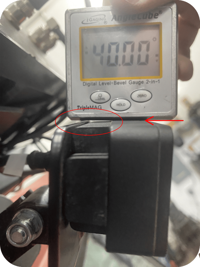
For accurate readings, the angle gauge should be placed on the top face of the camera, as shown in the right photo. The red-circled area highlights the air gap that was previously being measured incorrectly due to improper placement. The arrow points to the camera’s top face, which should be used as the reference surface for measuring roll or pitch.
| Incorrect | Correct |
 |
 |
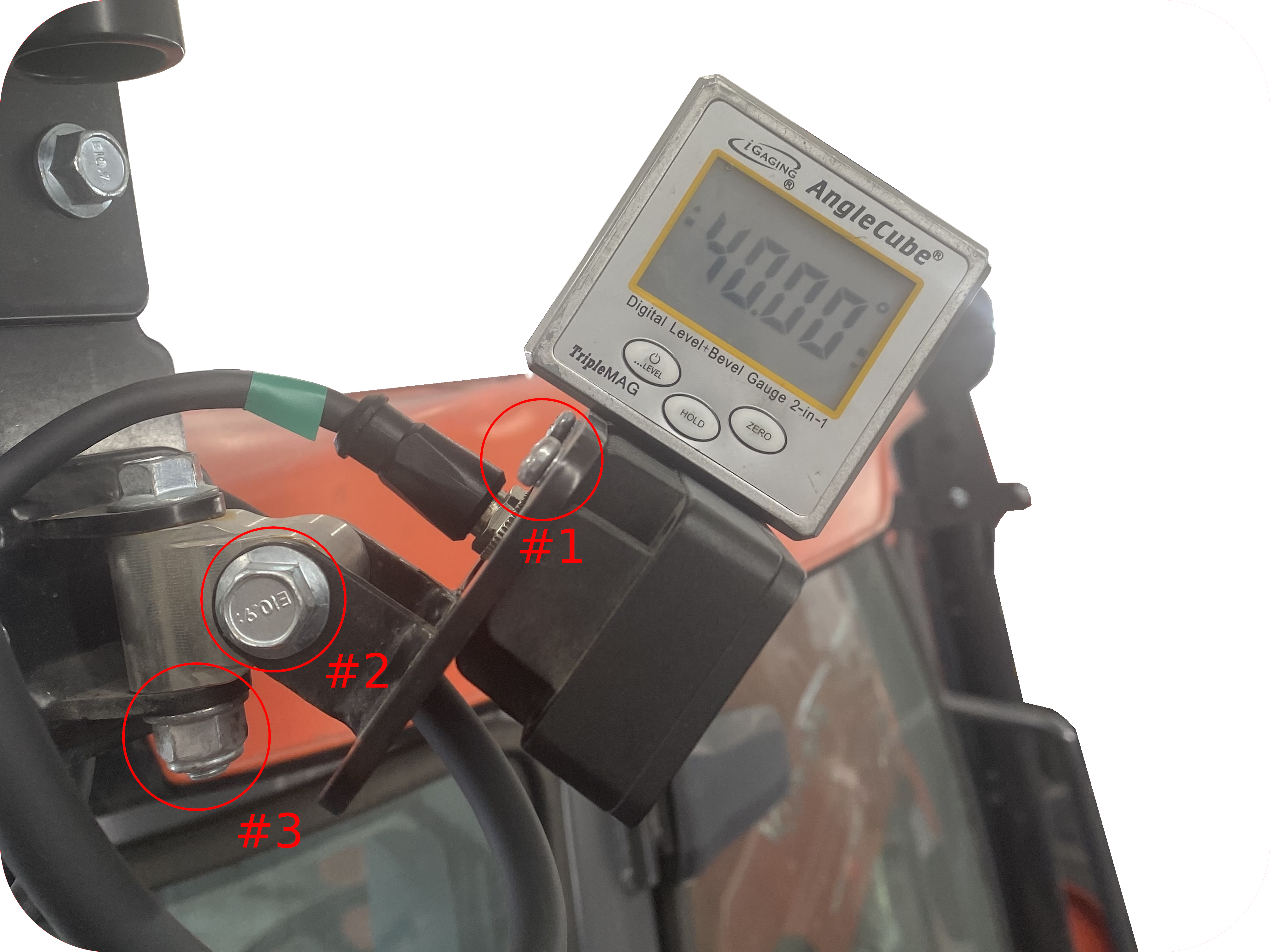
Tightening order
For each camera, follow the measurement and calibration order: Roll, Yaw, then Pitch. This sequence ensures the easiest workflow and the most accurate results.
When setting the angles, keep all adjustment hardware slightly loose until you have locked in the desired angle—just loose enough to allow movement with light hand pressure without the camera shifting freely. After measuring and calibrating an angle, tighten the adjustment hardware securely to prevent any movement.
Once the hardware for that axis is tightened, double-check your measurement to confirm it remains within spec. Since that axis is now fixed, you can be confident it stays accurate as you adjust the next one.
Following this sequence makes the workflow easier as you proceed, with more and more axes locked in place.
The image below depicts the order in which it is recommended to measure up, tighten the hardware, and input the calibrated angle.
Front Camera
Roll
Roll is not calibrate-able on the front camera in vMC and should be set to 0°.
A leftward (counterclockwise) camera tilt relative to level ground is considered negative, while a rightward (clockwise) tilt is positive.
The roll on the front camera should be adjusted to 0° as shown in the photo below.
Adjust the camera to the desired roll then tighten your hardware.

Yaw
Yaw cannot be adjusted or calibrated on the front camera.
Pitch
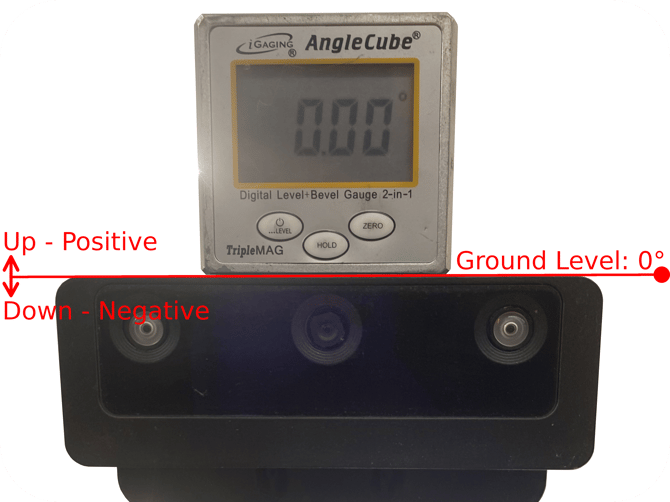
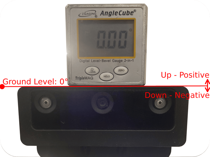
Zero the digital angle gauge on the flat surface where the vehicle is parked.
Next, place the gauge on the top surface of the camera.
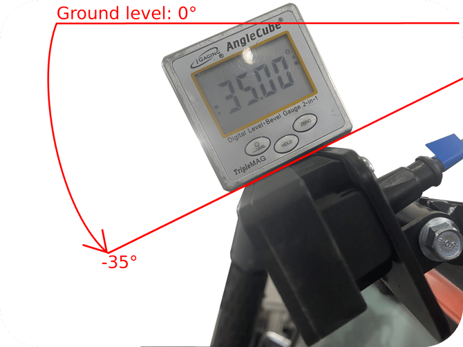
A downward camera angle, relative to the ground, is considered negative, while an upward angle is positive.
Adjust the camera to the desired pitch, tighten your hardware, re-verify your measurements, then enter the angle into the vMC calibration input.
The image below shows an example where the camera is angled down 35°.
Rear Camera
Roll
Roll is not calibrate-able on the rear camera in vMC and should be set to 0°.
A leftward (counterclockwise) camera tilt relative to level ground is considered negative, while a rightward (clockwise) tilt is positive.
The roll on the rear camera should be adjusted to 0° as shown in the photo below.
Adjust the camera to the desired roll then tighten your hardware.
Yaw
Yaw cannot be adjusted or calibrated on the rear camera.
Pitch
Zero the digital angle gauge on the flat surface where the vehicle is parked.
Next, place the gauge on the top surface of the camera.
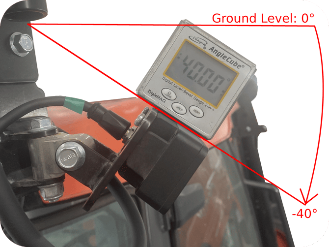
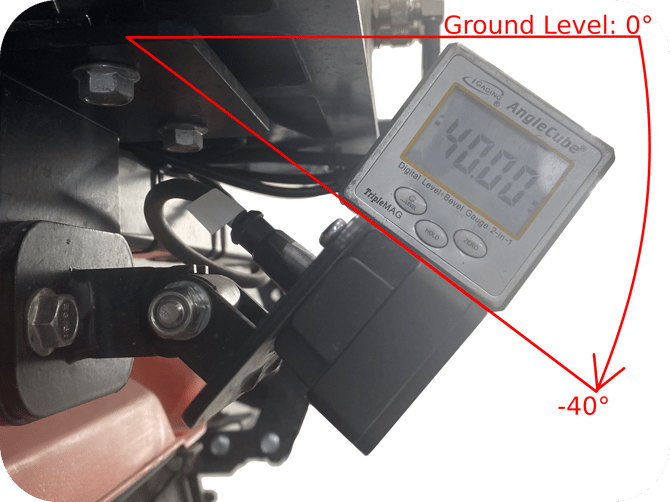
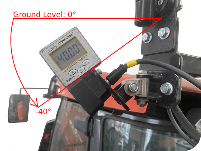
A downward camera angle, relative to the ground, is considered negative, while an upward angle is positive.
Adjust the camera to the desired pitch, tighten your hardware, re-verify your measurements, then enter the angle into the vMC calibration input.
The image below shows an example where the camera is angled down 40°.
Left Camera
Roll
Zero the digital angle gauge on the flat surface where the vehicle is parked.
Next, place the gauge on the top surface of the camera.
A leftward (counterclockwise) camera tilt relative to level ground is considered negative, while a rightward (clockwise) tilt is positive.
Adjust the camera to the desired roll, tighten your hardware, re-verify your measurements, then enter the angle into the vMC calibration input.
The image below shows an example where the camera has no roll at 0°.

Yaw
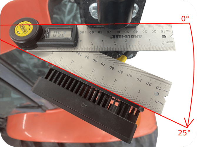
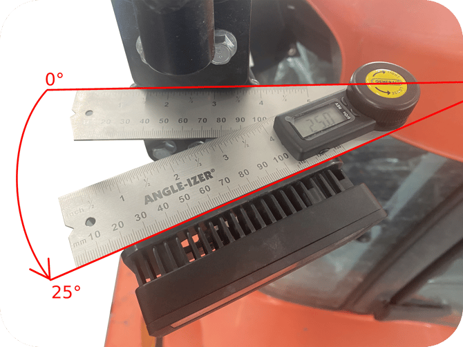
Zero the digital angle finder protractor on the flat surface of the antenna bracket.
Next, place the other end of the gauge on the back surface of the camera mounting bracket, just above the mounting hardware.
Rotating the camera toward the nose of the tractor is considered positive, while rotating it toward the rear is negative. The measurement is taken from the face of the antenna bracket to the back of the camera's mounting plate.
Adjust the camera to the desired yaw angle, tighten the hardware, re-verify the measurement, then enter the angle into the vMC calibration input.
The image below shows an example where the camera has a yaw value of 25°.
Pitch
Zero the digital angle gauge on the flat surface where the vehicle is parked.
Next, place the gauge on the top surface of the camera.
A downward camera angle, relative to the ground, is considered negative, while an upward angle is positive.
Adjust the camera to the desired pitch, then enter the negative angle into the vMC calibration input.
The image below shows an example where the camera is angled down 40°.
Right Camera
Roll
Zero the digital angle gauge on the flat surface where the vehicle is parked.
Next, place the gauge on the top surface of the camera.
A leftward (counterclockwise) camera tilt relative to level ground is considered positive, while a rightward (clockwise) tilt is negative.
Adjust the camera to the desired roll, tighten your hardware, re-verify your measurements, then enter the angle into the vMC calibration input.
The image below shows an example where the camera has no roll at 0°.
Yaw
Zero the digital angle finder protractor on the flat surface of the antenna bracket.
Next, place the other end of the gauge on the back surface of the camera mounting bracket, just above the mounting hardware.
Rotating the camera toward the nose of the tractor is considered positive, while rotating it toward the rear is negative. The measurement is taken from the face of the antenna bracket to the back of the camera's mounting plate.
Adjust the camera to the desired yaw angle, tighten the hardware, re-verify the measurement, then enter the angle into the vMC calibration input.
The image below shows an example where the camera has a yaw value of 25°.
Pitch
Zero the digital angle gauge on the flat surface where the vehicle is parked.
Next, place the gauge on the top surface of the camera.
A downward camera angle, relative to the ground, is considered negative, while an upward angle is positive.
Adjust the camera to the desired pitch, then enter the negative angle into the vMC calibration input.
The image below shows an example where the camera is angled down 40°.