![Sabanto-Horizontal-Orange-on-Transparent-RGB-1080px-05.16.23.png]](https://support.sabantoag.com/hs-fs/hubfs/Sabanto-Horizontal-Orange-on-Transparent-RGB-1080px-05.16.23.png?height=50&name=Sabanto-Horizontal-Orange-on-Transparent-RGB-1080px-05.16.23.png)
Package #0103-KT-4006 Material List
|
ITEM |
QTY |
PART # |
DESCRIPTION |
|||||||||||||||||||||||||||||||||||||||
|
1 |
1 |
9999-FP-3001A |
54035-118 AUTOPILOT PLATFORM KIT, M5 SERIES KUBOTA |
|||||||||||||||||||||||||||||||||||||||
|
Items consumed from the 54035-118 Trimble Platform Kit
|
||||||||||||||||||||||||||||||||||||||||||
|
2 |
2 |
9999-HH-2005A |
HOSE, VALVE PORTS A & B TO COUNTERBALANCE VALVE |
|||||||||||||||||||||||||||||||||||||||
|
3 |
2 |
9999-HH-2004A |
HOSE, STEERING CONTROLLER L/R TO COUNTERBALANCE VALVE |
|||||||||||||||||||||||||||||||||||||||
|
4 |
1 |
9999-HH-2003A |
HOSE, AUTOPILOT VALVE TANK RETURN PORT TO T12L TEE |
|||||||||||||||||||||||||||||||||||||||
|
5 |
1 |
9999-HH-2002A |
HOSE, TRACTOR PRESSURE LINE TO AUTOPILOT VALVE P-PORT |
|||||||||||||||||||||||||||||||||||||||
|
6 |
1 |
9999-HH-2001A |
HOSE, A.P. VLV EF PORT TO EW12L ON STEERING HAND PUMP P-PORT |
|||||||||||||||||||||||||||||||||||||||
|
7 |
4 |
9999-HF-1009A |
STRAIGHT THREAD CONNECTOR, -6 ORFS / -8 M ORB |
|||||||||||||||||||||||||||||||||||||||
|
8 |
2 |
9999-HF-1008A |
STRAIGHT THREAD ELBOW, -6 ORFS / -8 M ORB |
|||||||||||||||||||||||||||||||||||||||
|
9 |
3 |
9999-HF-1007A |
STRAIGHT THREAD ELBOW, -8 ORFS / -8 M ORB |
|||||||||||||||||||||||||||||||||||||||
|
10 |
2 |
9999-HF-1006A |
SWIVEL NUT ELBOW, -6 ORFS / -6 F ORFS SW |
|||||||||||||||||||||||||||||||||||||||
|
11 |
2 |
9999-HF-1005A |
3/8 SWIVEL NUT RUN TEE |
|||||||||||||||||||||||||||||||||||||||
|
12 |
2 |
9999-HF-1004A |
NPTF MALE W/ 60° CONE / BSPT 1/4-19 BSPP X 1/4-18 NPT |
|||||||||||||||||||||||||||||||||||||||
|
13 |
2 |
9999-HF-1003A |
FEMALE PIPE THREAD SWIVEL, -6 ORFS SWIVEL / 1/4-18 NPTF |
|||||||||||||||||||||||||||||||||||||||
|
14 |
1 |
9999-HF-1002A |
T UNION TEE, EO 24 DEG. CONE |
|||||||||||||||||||||||||||||||||||||||
|
15 |
2 |
9999-HF-1001A |
SWIVEL NUT ELBOW, 24° FLARELESS / FLARELESS SWIVEL |
|||||||||||||||||||||||||||||||||||||||
Hydraulic Fitting Cross Reference Table
|
Qty |
Parts Item # |
Parker Hannifin # |
Sabanto # |
Description |
|
4 |
8 |
6-8 F5OLO |
9999-HF-1009A |
STRAIGHT THREAD CONNECTOR, -6 ORFS / -8 M ORB |
|
2 |
9 |
6-8 C5OLO |
9999-HF-1008A |
STRAIGHT THREAD ELBOW, -6 ORFS / -8 M ORB |
|
2 |
10 |
8 C5OLO |
9999-HF-1007A |
STRAIGHT THREAD ELBOW, -8 ORFS / -8 M ORB |
|
2 |
11 |
6 C6LO-S |
9999-HF-1006A |
SWIVEL NUT ELBOW, -6 ORFS / -6 F ORFS SW |
|
2 |
12 |
6R6LO-S |
9999-HF-1005A |
3/8 SWIVEL NUT RUN TEE |
|
2 |
13 |
4-4FMK4S |
9999-HF-1004A |
NPTF MALE W/ 60° CONE / BSPT 1/4-19 BSPP X 1/4-18 NPT |
|
2 |
14 |
6 G6L-S |
9999-HF-1003A |
FEMALE PIPE THREAD SWIVEL, -6 ORFS SWIVEL / 1/4-18 NPTF |
|
1 |
15 |
T12L |
9999-HF-1002A |
T UNION TEE, EO 24 DEG. CONE |
|
2 |
16 |
EW12L |
9999-HF-1001A |
SWIVEL NUT ELBOW, 24° FLARELESS / FLARELESS SWIVEL |
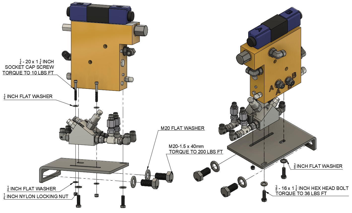
Install the Trimble Autopilot Platform Kit
| Note: The Trimble Autopilot Platform Kit includes installation instructions. The following steps are a supplement to clarify how to complete the installation. |
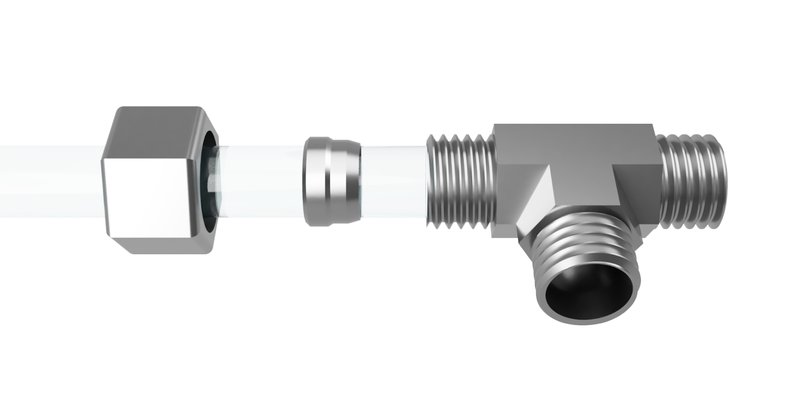
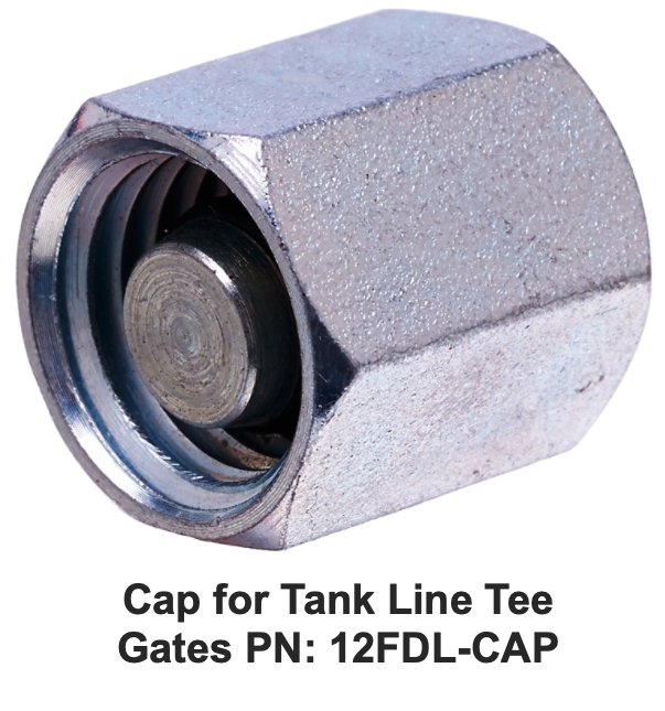
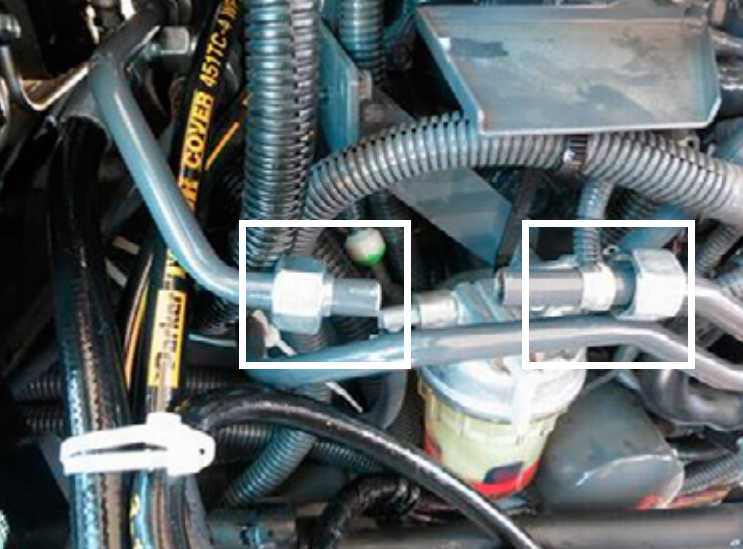
Step 1Install the oil return line tee:
Reference Note: If the hydraulic steering system needs to be removed from the tractor, a Gates 12FDL-CAP fitting can be used to cap the tee that is added to the tractor’s tank return line. |
|

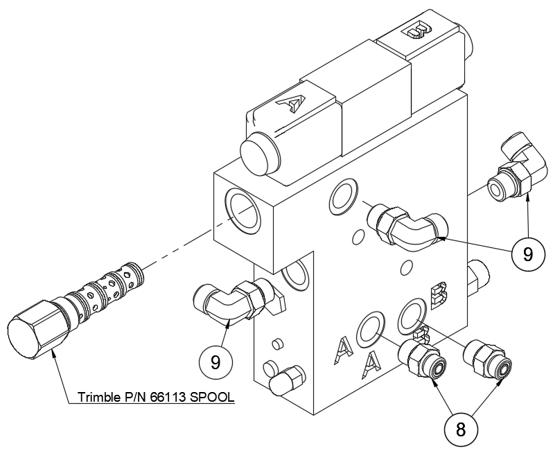
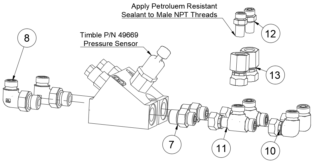
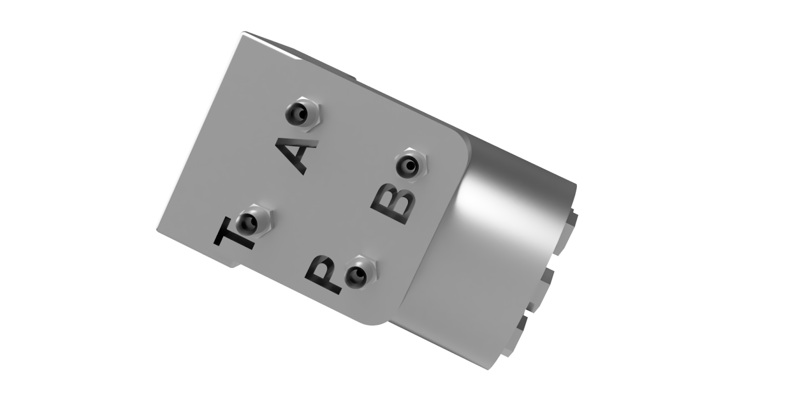
Step 2Assemble the Autopilot Steering Valve with the corresponding hydraulic fittings. |
|||||||||||||||||||||||||||||||||
|
Image 1. Autopilot Steering Valve Image 2. Counterbalance Valve Image 3. Assembled Valves |
|||||||||||||||||||||||||||||||||
Step 3Mount Valve Assemblies
|
|||||||||||||||||||||||||||||||||
Step 4
|
|||||||||||||||||||||||||||||||||
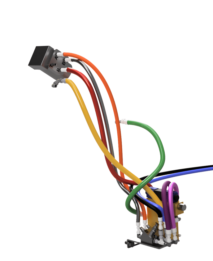
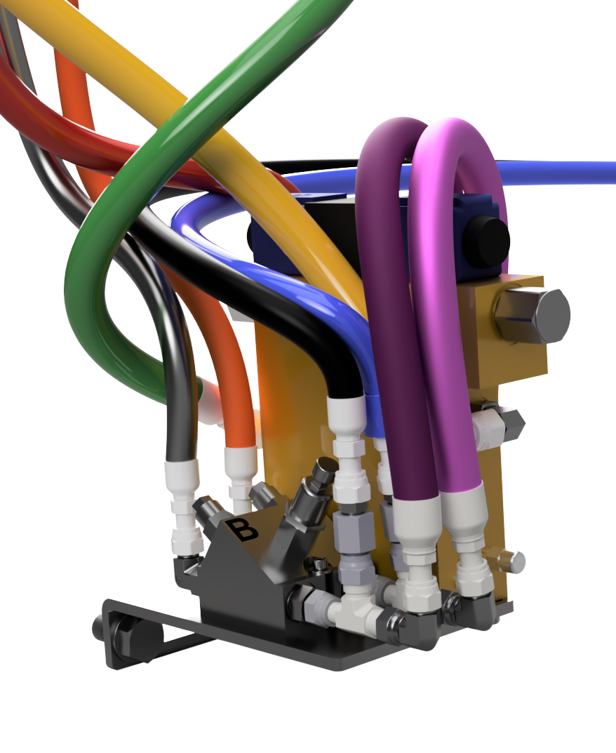
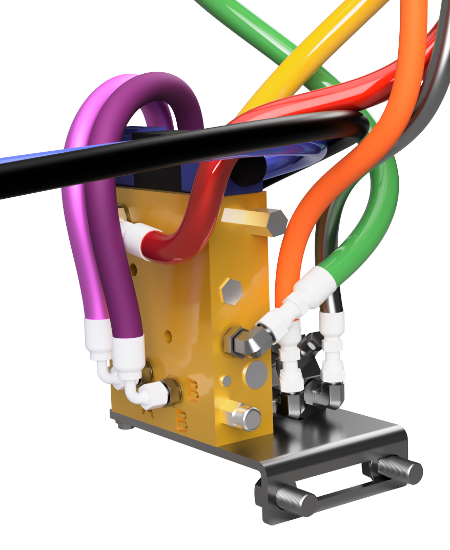
|
Hose Part Number |
Zip Tie Color |
Routing |
|
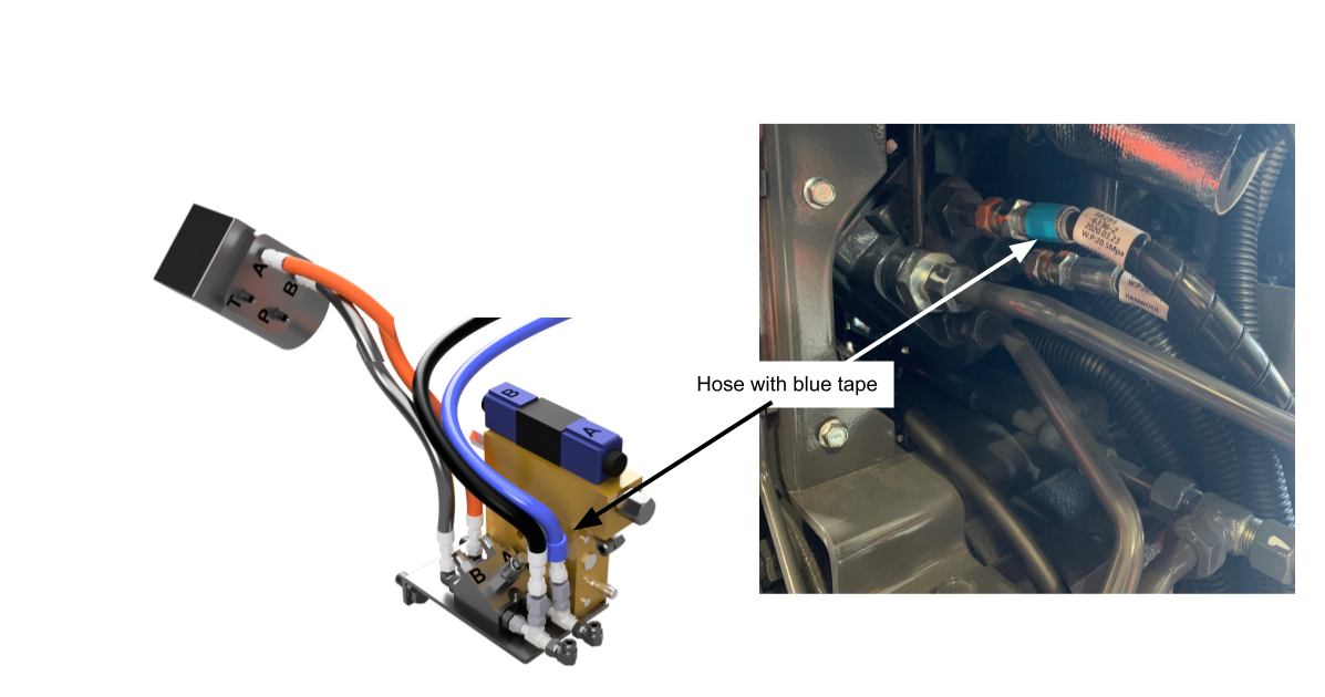
Existing (Blue Tape)** |
Blue |
Remove from hand-pump and attach to A2 |
|
Existing** |
Black |
Remove from hand-pump and attach to B2 |
|
9999-HH-2004A |
Orange |
A on hand-pump to A1 on Counterbalance Valve |
|
9999-HH-2004A |
Gray |
B on hand-pump to B1 on Counterbalance Valve |
|
9999-HH-2001A |
Red |
P on hand-pump to EF Port on Steering Valve |
|
9999-HH-2002A |
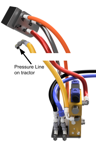
Yellow |
Elbows added to tractor pressure hardline to Pressure Port on Steering Valve |
|
9999-HH-2005A |
1-Purple |
Steering Valve “A” to Counterbalance Valve A3 (Light Purple) |
|
9999-HH-2005A |
2-Purple |
Steering Valve “B” to Counterbalance Valve B3 (Dark Purple) |
|
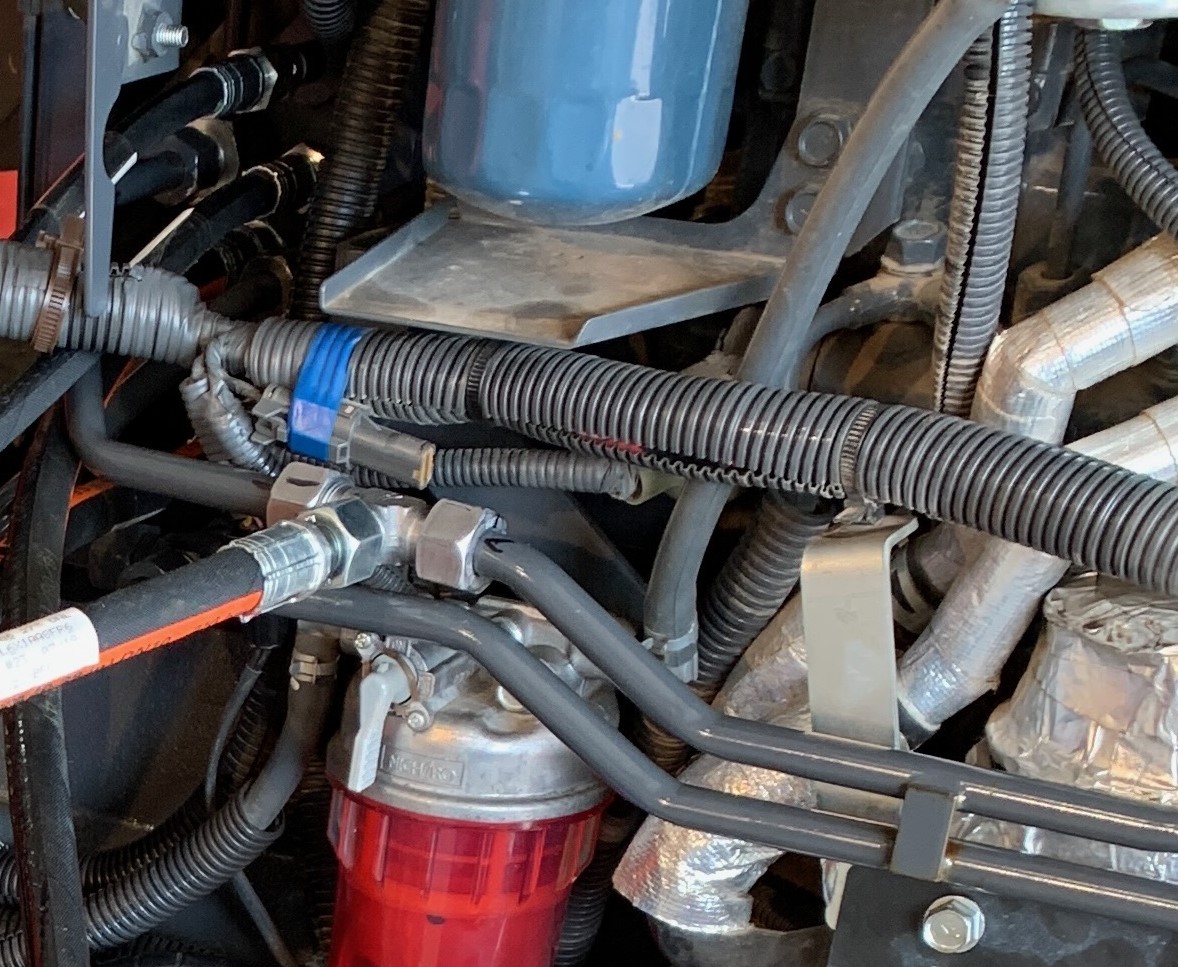
9999-HH-2003A |
Green |
Steering Valve Tank-port to Tee placed in steel oil cooler return line |
|
**Existing hoses on tractor that are connected to the front axle steering cylinder “Hand-Pump” refers to the radial pump on the tractor, connected to the steering wheel. “Steering Valve“ refers to Trimble steering manifold valve. “Counterbalance“ Valve refers to Trimble Counterbalance valve |
||
Step 4A
- Remove the factory hose with blue tape from Port A on the Steering Pump. Reattach the hose to the top of Counterbalance Valve A2.
- Remove the other factory hose from the steering pump and attach the hose to the top of Counterbalance Valve B2.
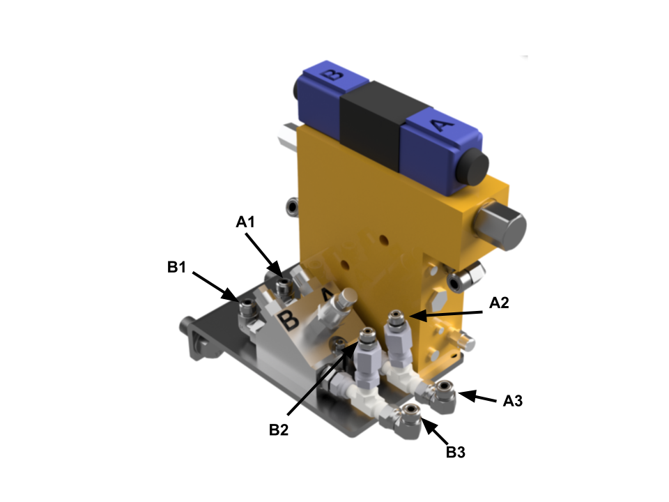
- Attach hose 9999-HH-2004A (Orange) to Port A1 on Counterbalance Valve and Port A on Steering Pump.
- Attach hose 9999-HH-2004A (Gray) to Port B1 on Counterbalance Valve and Port B on Steering Pump.
Step 4B
- Remove Hardline from Port C on Steering Pump. Attach hose 9999-HH-2001A (Red) to Port C on Steering Pump and to the Port EF on Steering Valve.
- Attach two 9999-HF-1001A elbows to the hard line previously on Steering Pump Port C, forming a U.
- Attach hose 9999-HH-2002A (Yellow) to the two elbows attached to the hardline. Attach other end to Port P on Steering Valve
Step 4C
- Connect hose 9999-HH-2005A (1-Purple/Light Purple) to Counterbalance Valve A tee and Steering Valve Port A3.
- Connect hose 9999-HH-2005A (2-Purple/Dark Purple) to Counterbalance Valve B tee and Steering Valve Port B3.
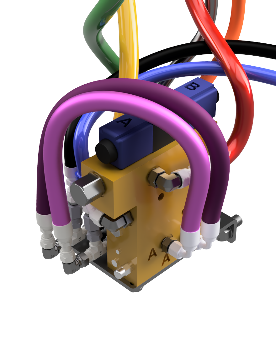
Step 4D
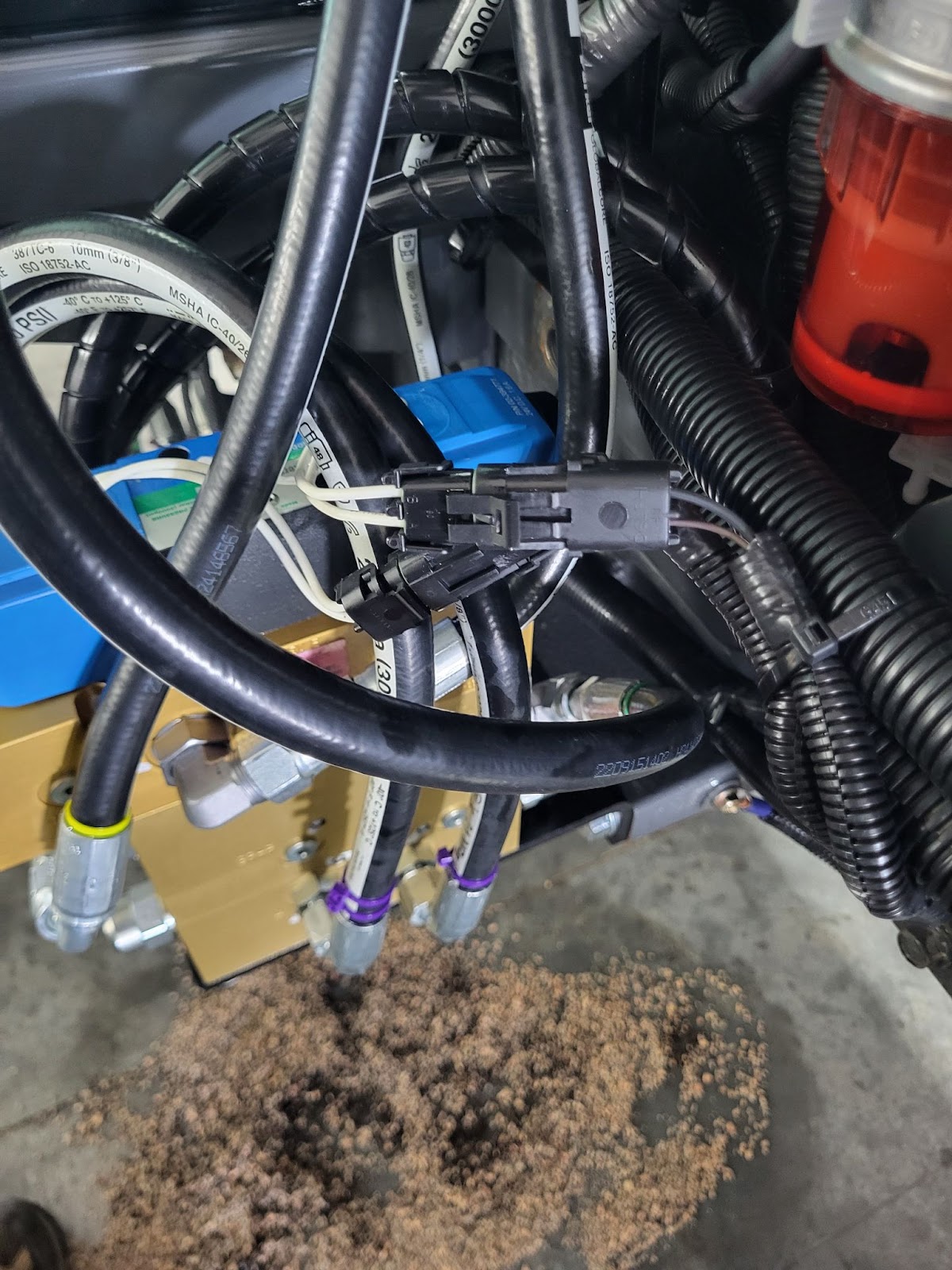
Connect solenoid valve connectors to the Sabanto vehicle wiring harness.
Make sure Steering Connector A & B on the vehicle harness are plugged into the corresponding connectors on the solenoid with solenoid B being nearest to the tractor.