![Sabanto-Horizontal-Orange-on-Transparent-RGB-1080px-05.16.23.png]](https://support.sabantoag.com/hs-fs/hubfs/Sabanto-Horizontal-Orange-on-Transparent-RGB-1080px-05.16.23.png?height=50&name=Sabanto-Horizontal-Orange-on-Transparent-RGB-1080px-05.16.23.png)
|
Theory of Operation Sabanto’s Steward kit comes complete with a set of electro-hydraulic remote valves. The Kubota M5 tractors come factory equipped with cable-actuated rear remote valves. For the sake of simplicity, Sabanto includes a 2-spool, double-acting remote valve with each Steward kit. Each valve spool is actuated by a pair of momentary on/off 12V electromagnetic coils. The valve, plus all necessary brackets, hardware, hydraulic hoses and fittings are included. |
 |
Rear Remote Valve Components
|
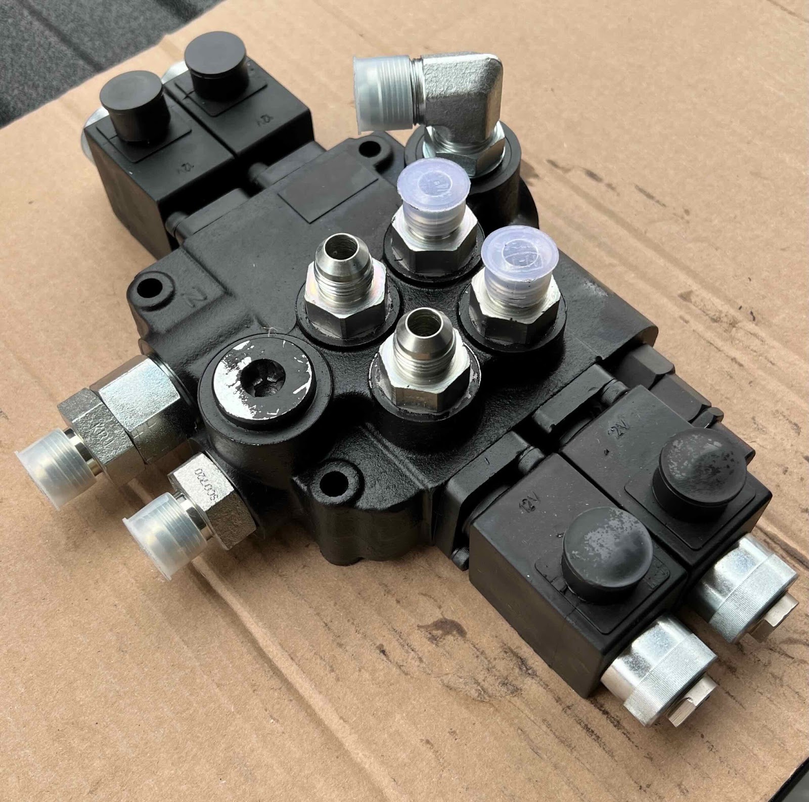
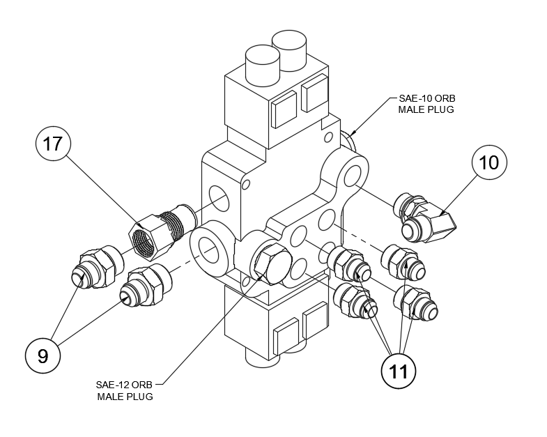
Remote Valve Assembly |
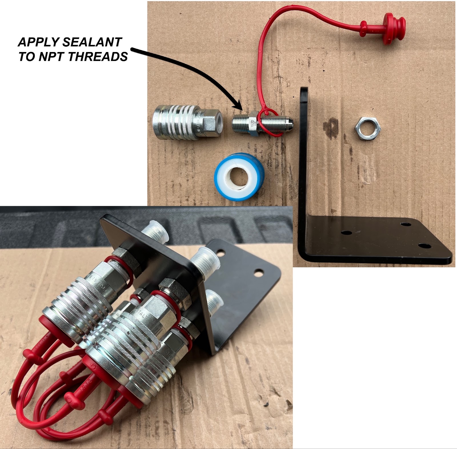
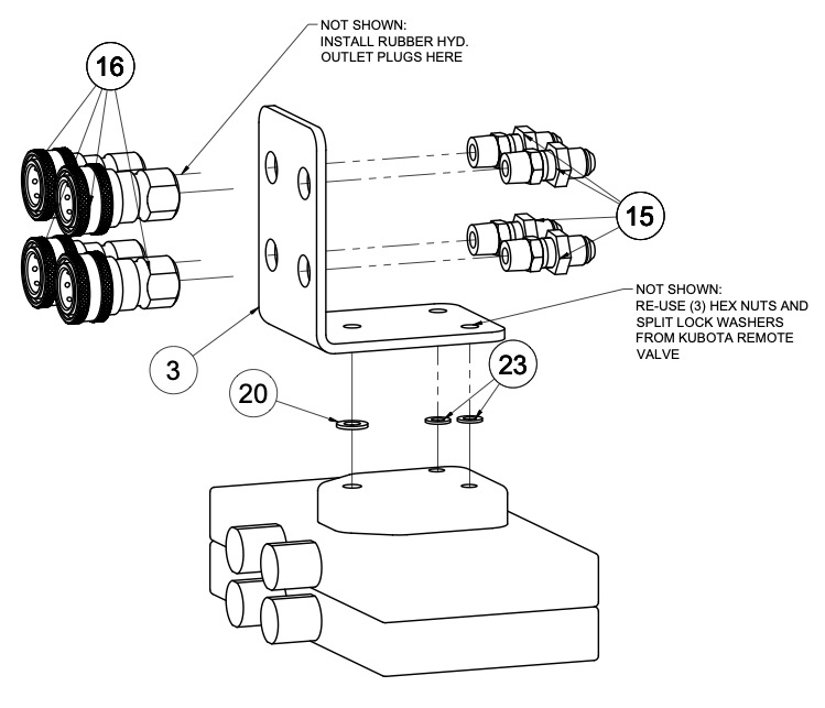
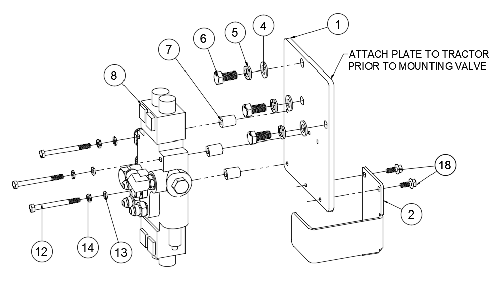
Remote Valve and Bracket Assembly |
|
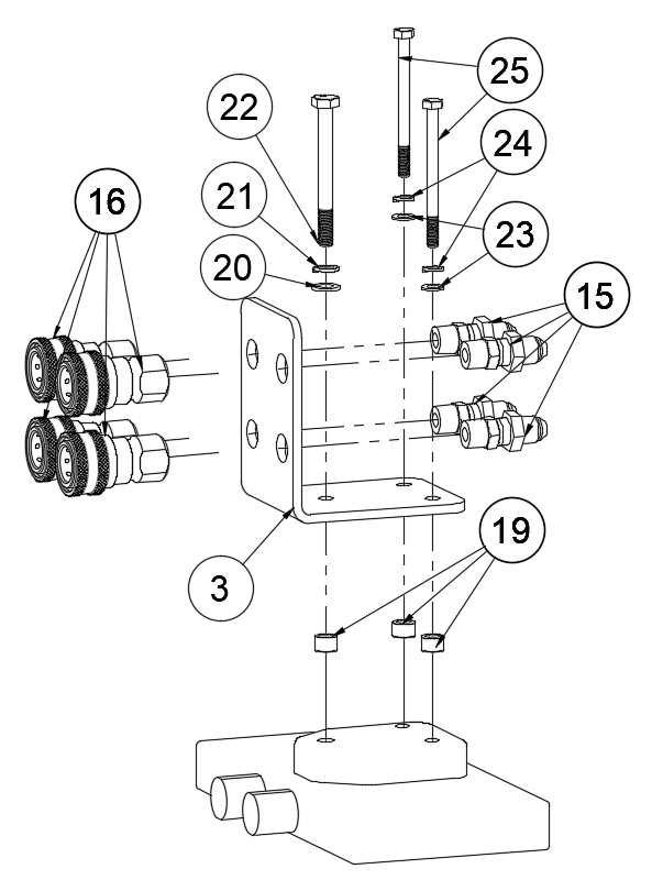
Remote Couplers For Models With Single Factory Rear Remote Valve |
Remote Couplers For Models With Multiple Factory Rear Remote Valve |

Package #: 0103-KT-4008 Material List
|
ITEM |
QTY |
PART NUMBER |
DESCRIPTION |
|
1 |
1 |
0102-MP-1016A |
PLATE, REAR REMOTE VALVE MOUNT |
|
2 |
1 |
0102-MP-1032A |
BRACKET, REMOTE VALVE GUARD |
|
3 |
1 |
0102-MP-1014A |
BRACKET, REAR REMOTE VALVE BLKHD |
|
4 |
3 |
9999-HA-1067A |
FLAT WASHER, M14 |
|
5 |
3 |
9999-HA-1066A |
SPLIT LOCK WASHER, M14 |
|
6 |
3 |
9999-HA-1065A |
HEX HEAD BOLT, M14-1.5, 30 MM LONG |
|
7 |
3 |
9999-HA-1052A |
SPACER, UNTHREADED, ⅜ ID |
|
8 |
1 |
9999-FP-3002A |
REMOTE VALVE, 2-SPOOL, 21 GPM, DOUBLE-ACTING |
|
9 |
2 |
9999-HF-1012A |
STRAIGHT ADAPTER, -12 MALE ORB TO -10 MALE JIC 37 |
|
10 |
1 |
9999-HP-1011A |
90° ADAPTER, -10 MALE ORB TO -10 MALE JIC 37 |
|
11 |
4 |
9999-HF-1014A |
STRAIGHT ADAPTER, -10 MALE O-RING BOSS TO -8 MALE JIC 37 |
|
12 |
3 |
9999-HA-1092 |
HEX HEAD BOLT, M8-1.25, 90 MM LONG, PARTIAL THREADED |
|
13 |
3 |
9999-HA-1005A |
FLAT WASHER, M8, 316 SS |
|
14 |
3 |
9999-HA-1006A |
SPLIT LOCK WASHER, M8, 316 SS |
|
15 |
4 |
9999-HF-1015A |
BULKHEAD/NUT, -8 JIC M X 1/2 NPT + 3/4-16 NUT |
|
16 |
4 |
9999-HF-1016A |
HYDRAULIC COUPLER, 1/2 ISO AG X 1/2 FEMALE NPT |
|
17 |
1 |
9999-HF-1010A |
ADAPTER SLEEVE, POWER BEYOND (FOR P80 & Z80 VALVES) |
|
18 |
2 |
9999-HA-1017A |
FLANGED HEX HEAD BOLT, M8-1.25 MM, 20 MM LONG |
|
19 |
3 |
9999-HA-1094 |
UNTHREADED SPACER, M10, 10 MM LONG X 16 MM OD |
|
20 |
2 |
9999-HA-1095 |
FLAT WASHER, M10 |
|
21 |
1 |
9999-HA-1096 |
SPLIT LOCK WASHER, M10 |
|
22 |
1 |
9999-HA-1097 |
HEX HEAD SCREW, M10-1.25, 100 MM LONG |
|
23 |
4 |
9999-HA-1098 |
FLAT WASHER, M8 |
|
24 |
2 |
9999-HA-1099 |
SPLIT LOCK WASHER, M8 |
|
25 |
2 |
9999-HA-1100 |
HEX HEAD SCREW, M8-1.25, 100 MM LONG |
|
26 |
2 |
9999-EH-2001A |
SWITCH BOX, MOMENTARY ON/OFF CONTROL FOR 2-SPOOL VALVE |
|
27 |
1 |
9999-EH-2005 |
HARNESS, 2-SPOOL / 4-SOLENOID |
|
28 |
1 |
9999-HH-2006A |
HOSE, RM VLV PRESSURE -- (27 IN HOSE LENGTH) |
|
29 |
1 |
9999-HH-2007A |
HOSE, POWER BEYOND -- (16 IN HOSE LENGTH) |
|
30 |
1 |
9999-HH-2008A |
HOSE, TANK RETURN -- (13.5 IN HOSE LENGTH) |
|
31 |
1 |
9999-HH-2009A |
HOSE, RM VLV REAR SLICE-TOP RR OUTLETS -- (68” HOSE) |
|
32 |
1 |
9999-HH-2010A |
HOSE, RM VLV FRONT SLICE-BOTTOM RR OUTLETS -- (67” HOSE) |
Check hydraulic pressure of system
Before proceeding with the installation of this remote valve kit, we suggest checking the operating pressure of the system. After this remote valve kit is installed, it may be necessary to adjust the relief valve of the 2-spool valve, such that it isn't below that of the tractor's relief valve setting.
|
With the tractor's engine turned off, Connect a pressure gauge that is rated up to 3000 psi to any of the tractor's rear remote valve ports |
 |
|
With the following conditions, actuate the remote valve that the gauge is connected to:
Oil Temp:
|
The factory specifications are:
If the pressure isn't to spec, consult your Kubota dealer to adjust the tractor's relief valve setting. |
Install the Rear Remote Valve - Tractor w/o Loader
Preassemble ValveWrenches Required: 1” and 1 ¼” for fittings, phillips screwdriver |
|
Preassemble Bulkhead componentsWrenches Required: 1” and 1 ⅛” for fittings
|
|
Assemble brackets to tractor frame
|
 |
Attach Bulkhead assembly to OEM remote valve stackMount rear remote valve bracket and fittings:
|
 |
|
For tractors with a single OEM remote, utilize the longer M8 and M10 bolts, spacers, and washers included with this kit. |
For tractors with multiple OEM remotes, utilize existing studs and hardware. Place a M10 and (2) M8 flat washers between the bulkhead bracket and the remote valve stack-cap. |
Pressure, Power Beyond, and Case Drain Plumbing
Note: Hydraulic hoses are marked with colored zip ties that correspond to the diagram below.
|
|
|
|
|
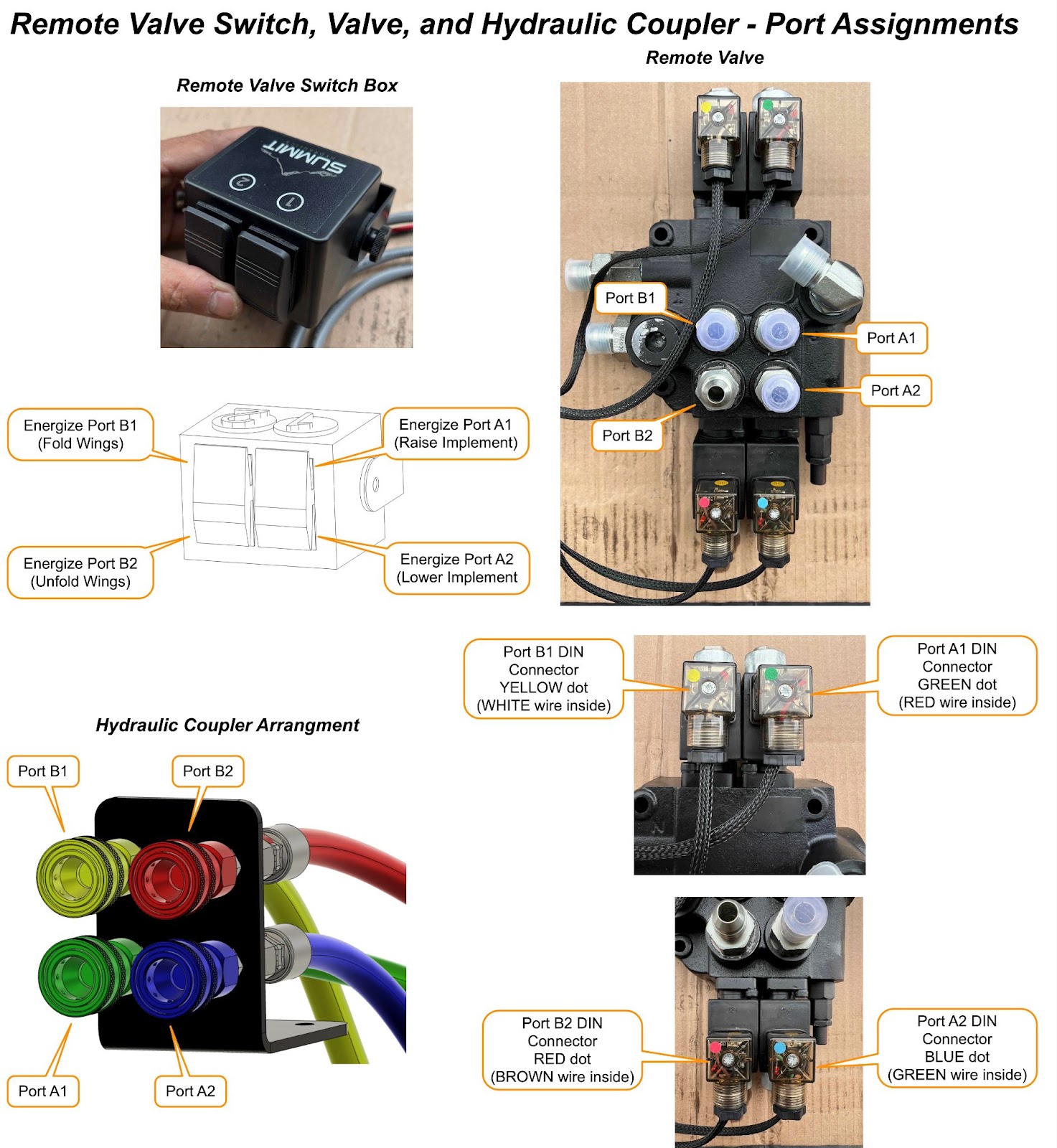
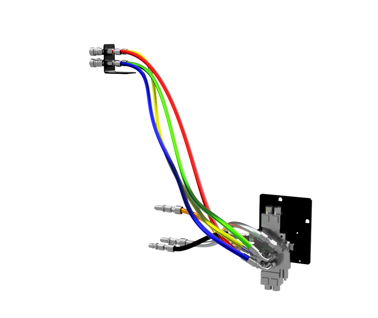
Remote Valve Port and Hydraulic Coupler PlumbingTHEORY OF OPERATION: The remote valve included within the Steward™ kit is a 2-spool momentary on and off. The intended use of the spool A is for pull-type implement raise and lower. Spool B is for pull-type implement wing fold/unfold.
|
|
Remote Valve Port and Hydraulic Coupler Plumbing (cont’d)
Note: Hydraulic hoses are marked with colored zip ties that correspond to the following diagram
|
|
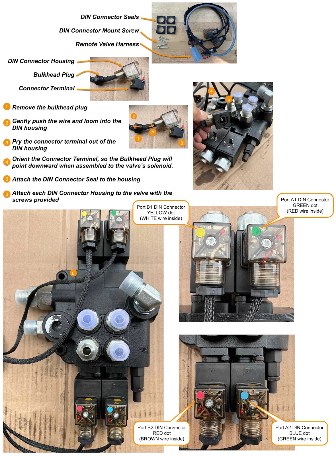
Attach Remote Valve Harness to the solenoids |
|
Install the Rear Remote Valve Guard
|
|
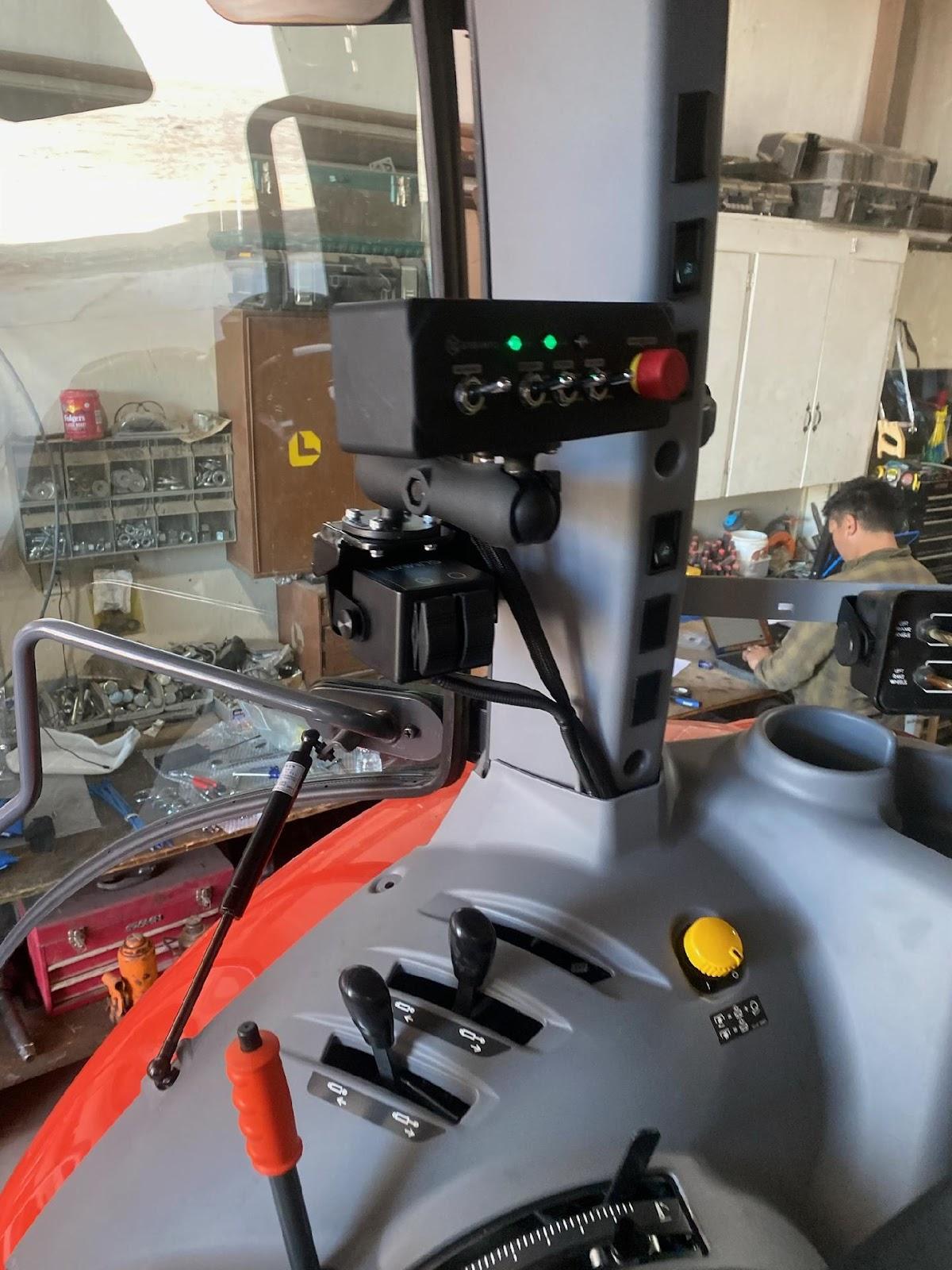
Install and Connect Switch box - Cab
|
|
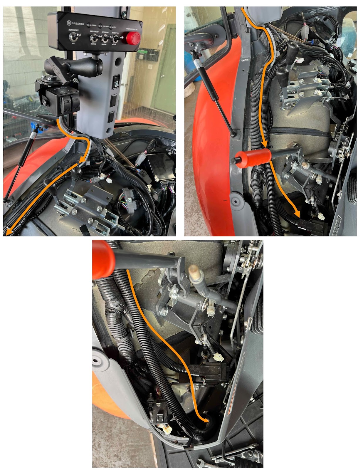
Routing of Sw. box harness - Cab and ROPS
|
|
Adding 2-cavity connector to Sw. box harness and connecting to vehicle harness - Cab and ROPS |
|
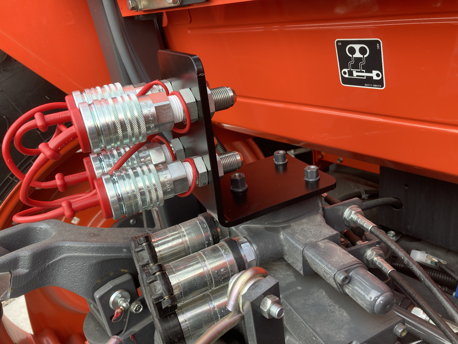
Reference Images
|
|