![Sabanto-Horizontal-Orange-on-Transparent-RGB-1080px-05.16.23.png]](https://support.sabantoag.com/hs-fs/hubfs/Sabanto-Horizontal-Orange-on-Transparent-RGB-1080px-05.16.23.png?height=50&name=Sabanto-Horizontal-Orange-on-Transparent-RGB-1080px-05.16.23.png)
Accurate implement measurements are essential for field operations. These values allow the system to understand how the implement behaves and how to use it effectively. The primary uses for these measurements are:
- Coverage Planning: Calculating how much area the implement covers and planning the most efficient path to cover the entire field.
- Path Planning: Ensuring the vehicle drives in the right place to make perfectly straight rows, even on contoured ground.
- Collision Detection: Making the vehicle aware of the implement's full dimensions to avoid collisions with obstacles, especially during turns.
The required measurements depend on how the implement is attached. This guide provides extra detail to help you capture them correctly.
Table of contents
Note: It is not required for the implement to be attached to the vehicle to complete an implement measure up.
Important: Before measuring up the implement, please navigate to the "Capabilities" on vMC, and turn on any applicable capabilities for the implement.
Center of Drawbar Connection to Implement
The distance between the center of the connection point on the implement where the drawbar pin will be placed, to the front of the implement.
Why it's important: This measurement helps accurately track and control the position of the implement relative to the tractor. This ensures precise path following, safe maneuvering, and effective operation in the field.
Silhouette View
|
|
Center View
|
|
Left View
|
Right View
|
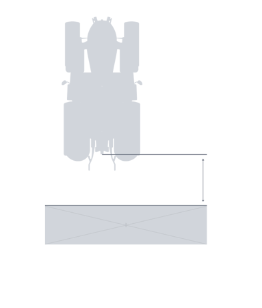
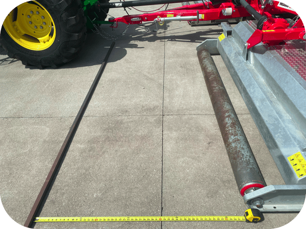
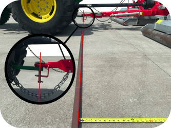
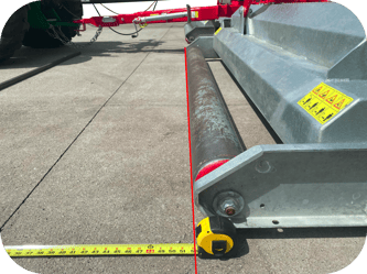
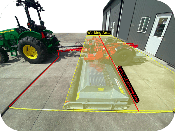
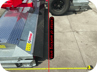
Drawbar Connection to Center of Work Area
The distance between the center of the connection point on the implement where the drawbar pin will be placed, to the center of the implements working area.
Why it's important: This measurement allows the autonomy system to determine the exact location of the implement’s working section relative to the tractor. This ensures accurate coverage, precise path planning, and effective operation during autonomous tasks.
Silhouette View
|
|
Center View
|
|
Left View
|
Right View
|
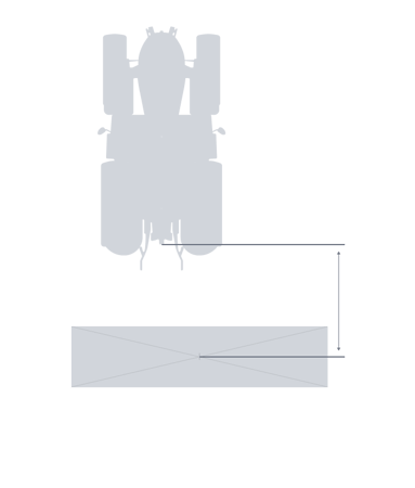
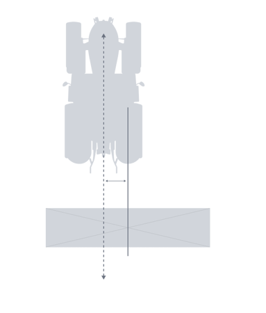
Left/Right Offset
Path planning with an offset is not formally supported yet.
The offset distance either left (negative) or right (positive) from the vehicle's center axis.
Why it's important: This is for implements that are not perfectly centered behind the vehicle. An accurate offset is critical for path planning, as the system needs to adjust the vehicle's path to ensure the implement is in the correct location, not the vehicle itself.
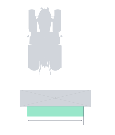
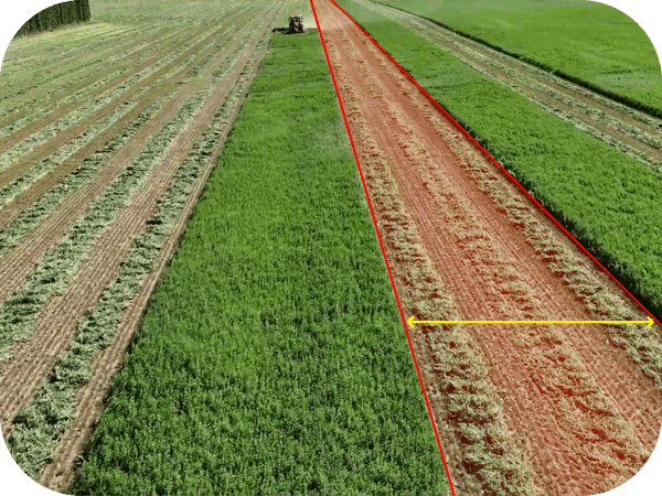
Working Width
Working Width is not officially used for any features yet.
The maximum width of the implement's working area (e.g., the width of product that a sprayer will broadcast).
Why it's important: This measurements allows the system to understand how much area the implement actually covers. This value is critical for generating coverage maps after completing a mission and other alike features in the future.
Silhouette View
|
|
Center View
|
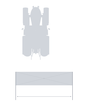
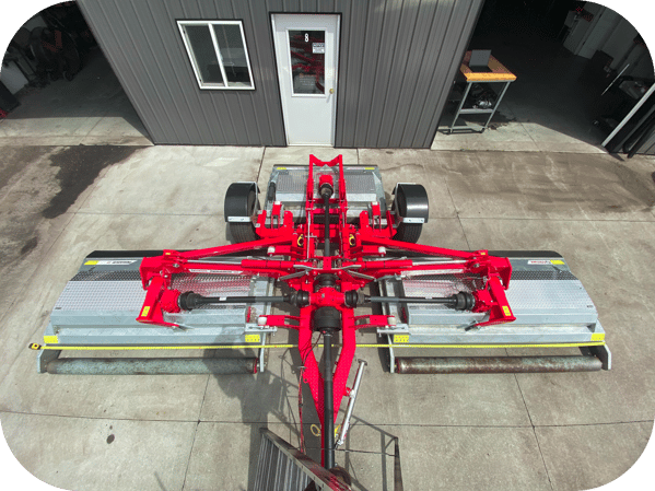
Implement Width
The maximum physical width of the implement when it is in its working position. (e.g a wing fold implement has the wings unfolded)
Why it's important: This defines the implement's total horizontal footprint. The system uses this to avoid collisions, ensuring that the implement's wings or outer edges don't hit obstacles like fence posts or trees while working in the field.
Silhouette View
|
|
Center View
|
|
Left View
|
Right View
|
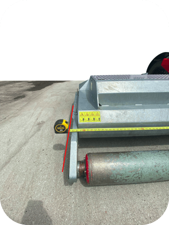
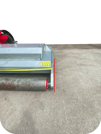
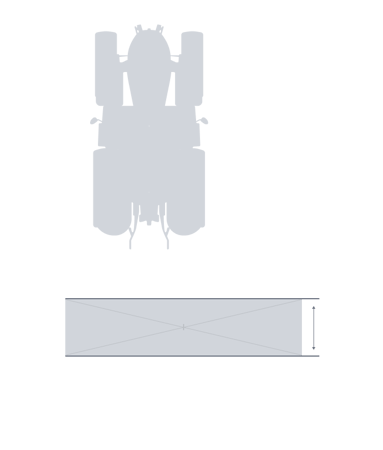
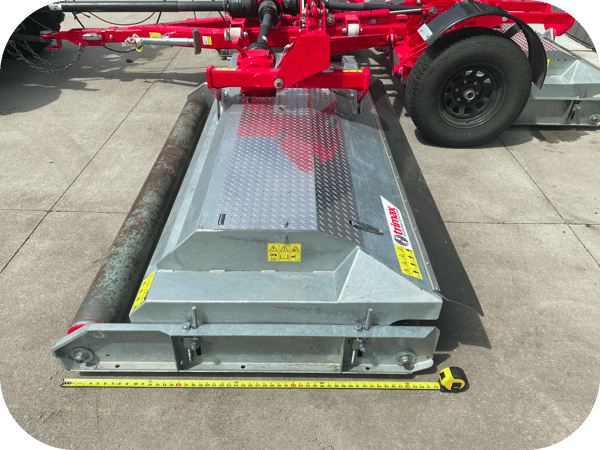
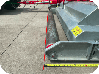
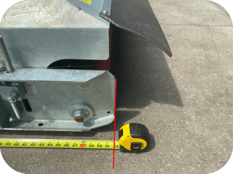
Implement Length
The maximum length of the implement's working area, excluding the attachment point (e.g., from the back of the planter to the front of the seed boxes), and the center trailing section length if needed.
Why it's important: This measurement helps the Sabanto autonomy system create an accurate 3D model and understand the implement's size. It's used in visualizations and to help the vehicle understand how much space the implement occupies for geofence detection purposes.
Silhouette View
|
Silhouette View
|
Center View
|
|
Left View
|
Right View
|
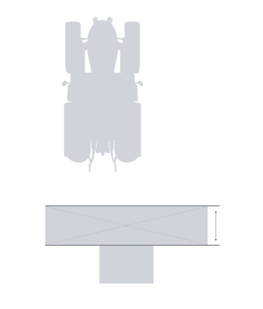
Center Trailing Section Length
The length of the center trailing sections working area.
Why it's important: This measurement helps the Sabanto autonomy system create an accurate 3D model and understand the implement's size. It's used in visualizations and to help the vehicle understand how much space the implement occupies for geofence detection purposes.
Silhouette View
|
|
Center View
|
|
Left View
|
Right View
|
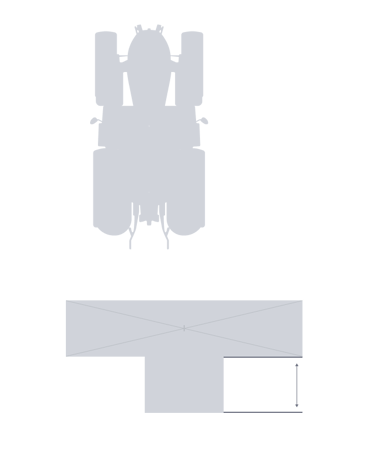
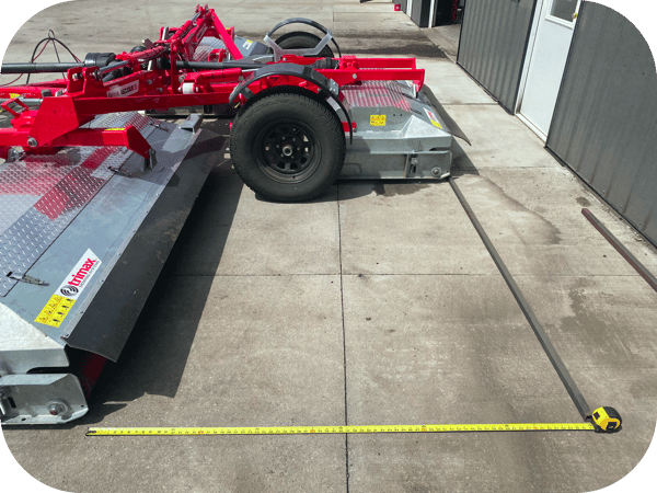
Center Trailing Section Width
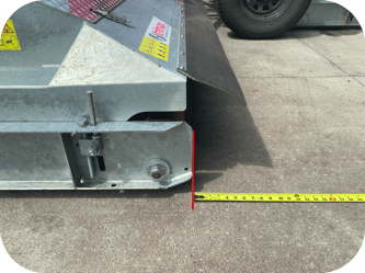
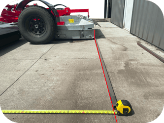
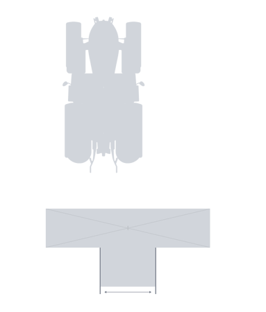
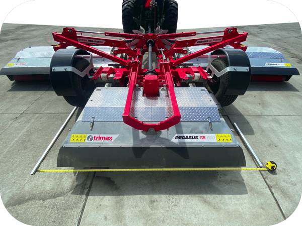
The maximum physical width of the implements center trailing section. (e.g any implement shaped like a "T" instead of a rectangle.)
Why it's important: This defines the implement's horizontal footprint for the center trailing section.
This measurement helps more accurately represent the implement's true shape instead of a simple rectangle which helps prevent false geofence detections.
Silhouette View
|
|
Center View
|
|
Left View
|
Right View
|
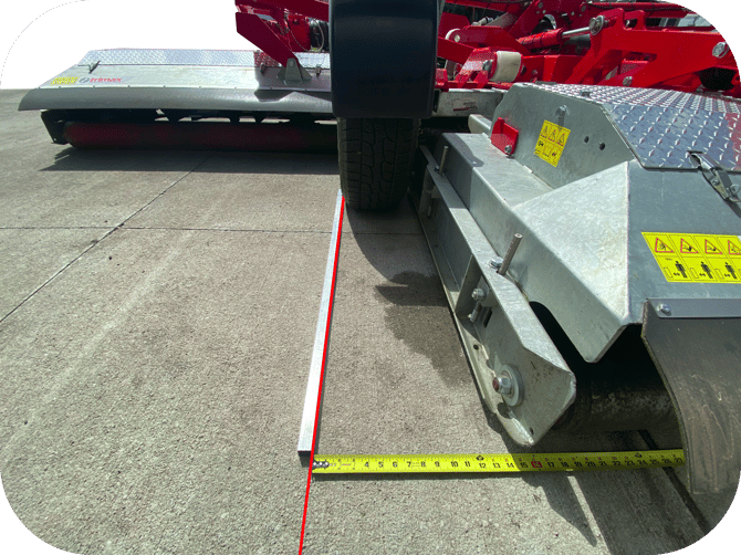
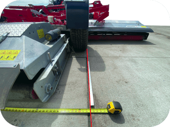
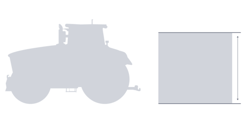
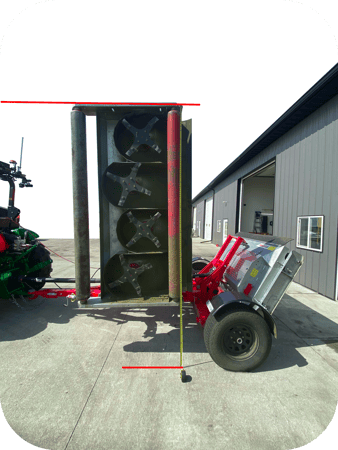
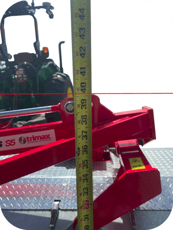
Implement Height
The maximum height of the implement while in the working position. (e.g a wing fold implement has the wings unfolded)
Why it's important: This is used for visualization and obstacle detection. It helps generate an accurate 3D model and can be used to avoid overhead obstacles that might be present in the field, but not within the implements or tractors 3D geometry.
Silhouette View
|
Center View
|
Right View
|
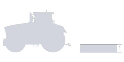
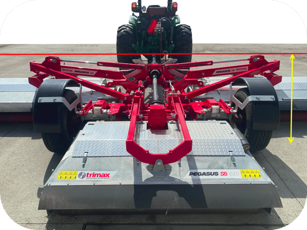
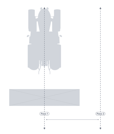
Swath Width
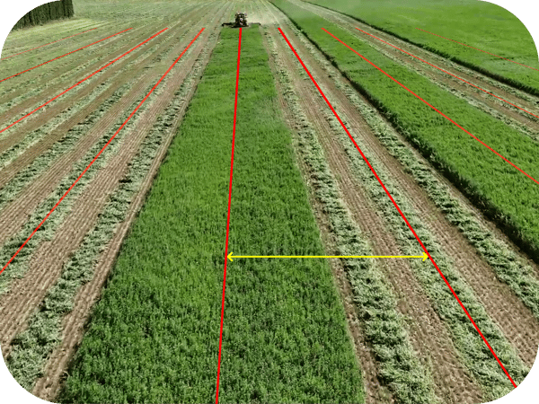
The planned spacing between passes. When generating coverage plans or templates, this value will be used to space apart coverage passes.
When considering total field coverage: A swath width smaller than a working width results in overlap while working a field. A swath with larger than a working width results in a skip between passes.
When considering total field coverage: A swath width smaller than a working width results in overlap while working a field. A swath with larger than a working width results in a skip between passes.
Why it's important: This value directly controls the path planner. By setting a swath width, you define exactly how far apart you want each pass to be, giving you control over overlap or gap/skip to match your specific operational needs. This value serves as a default and is editable on the coverage planner screen.
Silhouette View |
|
Arial View
|
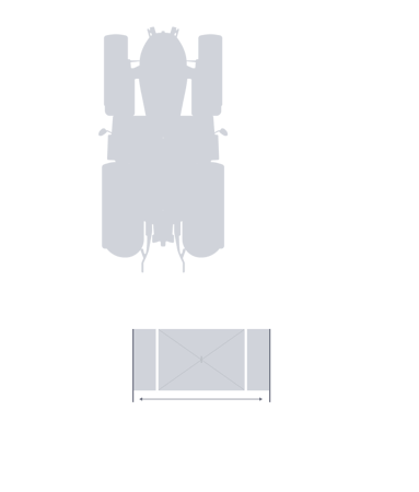
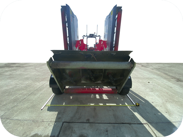
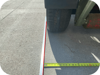
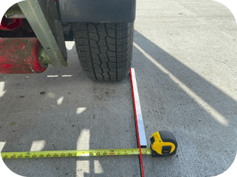
Folded Implement Width
The maximum physical width of the implement when the wings are in a folded position.
Why it's important: This defines the implement's total horizontal footprint when folded. The system uses this to avoid collisions and prevent false obstacle positives when navigating thin paths with obstacles on either side of the vehicle.
Silhouette View
|
|
Center View
|
|
Left View
|
Right View
|
Folded Implement Height
The maximum height of the implement while in the working position.
Why it's important: This is used for visualization and obstacle detection. It helps render an accurate 3D model of the implement and ensures that tall obstacles are detected when the implement is folded.
Silhouette View |
|
Center View
|