![Sabanto-Horizontal-Orange-on-Transparent-RGB-1080px-05.16.23.png]](https://support.sabantoag.com/hs-fs/hubfs/Sabanto-Horizontal-Orange-on-Transparent-RGB-1080px-05.16.23.png?height=50&name=Sabanto-Horizontal-Orange-on-Transparent-RGB-1080px-05.16.23.png)

Table Of Contents (Quick Search)
- Digital Angle Finder - Zeroing
- iPhone - Measure App - Zeroing
- Hardware Installation
- Software & Firmware Setup
- Theory of Operation
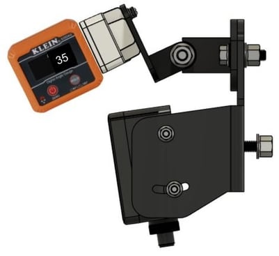
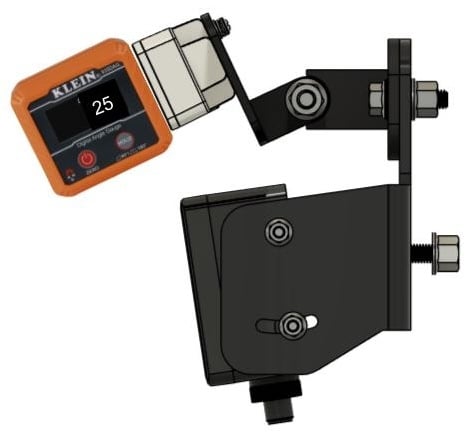
Digital Angle Finder - Zeroing
IMPORTANT TIP: Before radar assembly, park the vehicle on a flat level surface. Although the surface may not be perfectly level, you can "zero" your digital angle finder with respect to the surface that the vehicle is parked on.
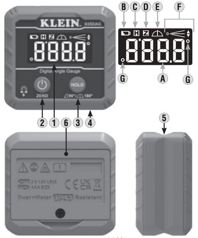
Using the Klein Tools 935DAG digital angle finder as an example:
To set a reference plane, press the Power/ZERO Button (2) . The measurement value on the display will blink once and change to 0.0° and the ZERO icon (D) will show on the display. At this point, all new measurement values will be in reference to this user-set reference plane. To return to measuring true level, press the Power/ZERO Button 2 .
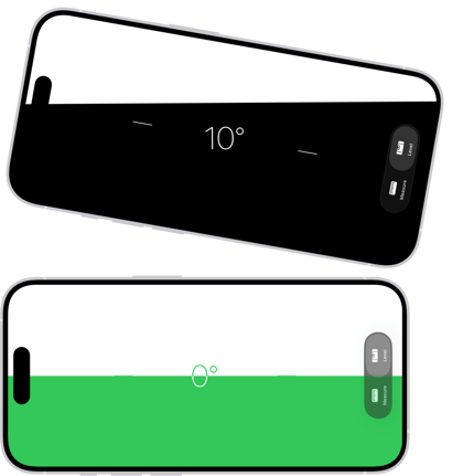
iPhone - Measure App - Zeroing
IMPORTANT TIP: If using an iPhone Measure App as a level; zero the iPhone against the ground surface where the tractor is parked.
-
Go to the Measure app (in the Utilities folder) on your iPhone.
-
Set the phone on the same ground surface as the vehicle.
-
Tap the screen to capture the slope of the ground surface.
-
Hold iPhone against the radar to set the angle
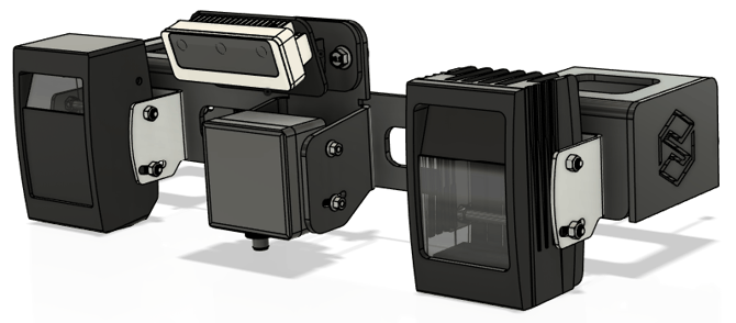
Hardware Installation
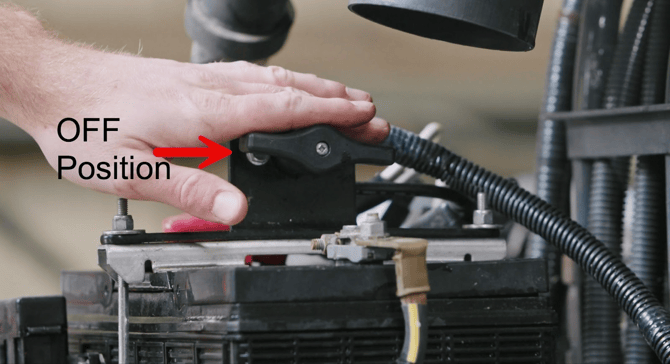
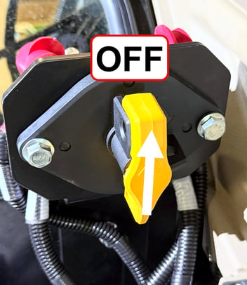
IMPORTANT: Turn OFF the battery disconnect for the Autonomy System. For Kubota tractors, this will be under the hood on the battery as shown, for John Deere models it will be near the operator's seat.
Battery Disconnect Switch for Systems without an Audio, Visual, & Light Kit (AV&L) shown below
Battery Disconnect Switch for Systems with an Audi, Visual, & Light Kit (AV&L) shown below
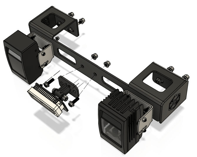
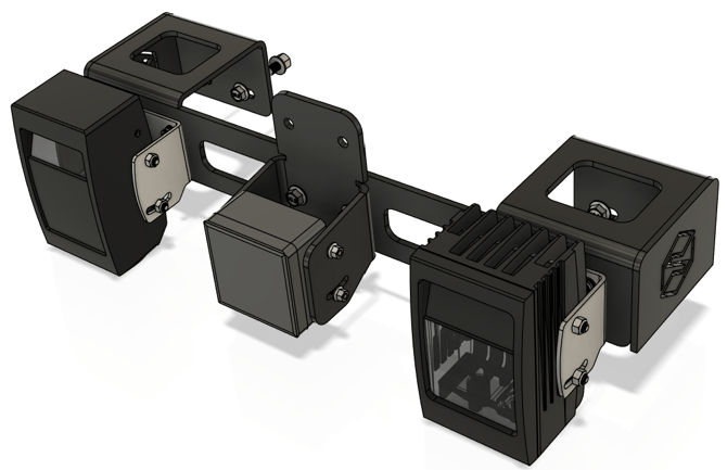
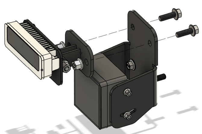
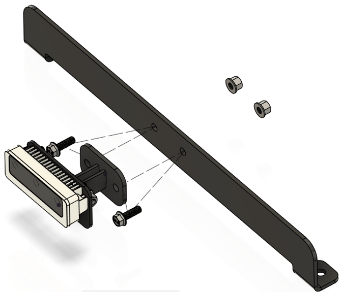
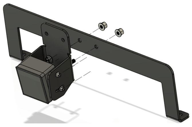
Step 1: Assemble the IFM Radar sensor to its mounting bracket. Don’t yet tighten the M5 bolts all the way, leave them loose enough for the sensor to rotate. Don’t install M8 nylock nuts yet.
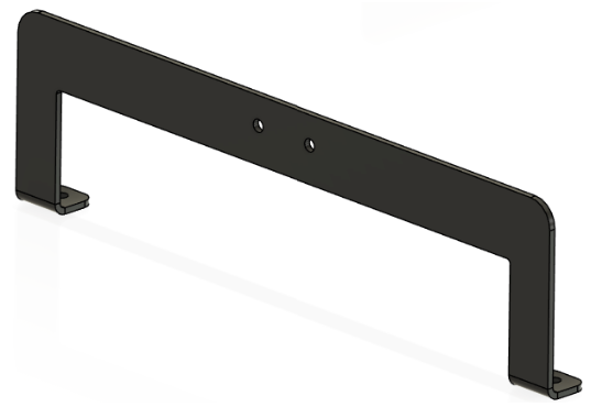
Parts List
| ITEM | QTY | PART NUMBER | DESCRIPTION |
|
1 |
1 | 9999-MP-1050 | PLATE, FORMED, CAB/ROPS RADAR MOUNT |
| 3 | 1 | 9999-DD-1022 |
SENSOR, RADAR AREA |
| 4 | 2 | 9999-HA-1274 | SCREW, M5-0.8 X 100MM, SHCS, SS |
| 5 | 2 | 9999-HA-1135 | NUT, M5-0.8, NYLOC, FH, ZP |
| 7 | 2 | 9999-HA-1132 | SCREW, M8-1.25 X 25MM, FHHCS, ZP |
| 7 | 2 | 9999-HA-1128 | NUT, M8-1.25, NYLOC, FH, ZP |

Cab Model Install
Before proceeding, ensure you have completed the steps in the "Hardware Installation" section.
Step 1: Locate and remove the front camera assembly on the front edge of the cab.
Step 2: Bolt the radar assembly in place of the front camera
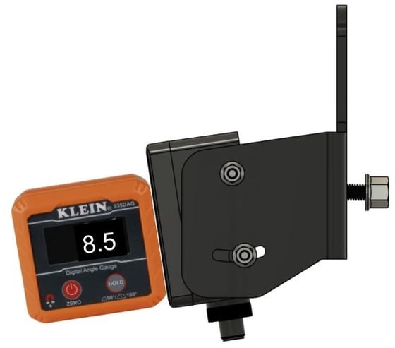
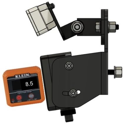
Step 3: Using a digital angle finder, set the angle of the radar at 8.5 degrees down relative to the ground plane and tighten the two M5 mounting bolts.
Step 4: Remount the front camera assembly using the top two holes of the radar bracket.
Step 5: Adjust the camera angle. For cab models, set the angle to 35 degrees down relative to the ground.
Step 6: Install the harness. Locate the connector labeled “IFM” near the rear of the roof. The O3M infrared sensors on the front of the cab will be plugged into the needed harness. Depending on which version of the harness you have, you will either find a pigtail labeled “RADAR” which you will use. If there is no pigtail then you will be teeing into the existing harness.
Setup when your O3M harness does have a pigtail labeled "Radar"

Setup when your O3M harness does not have a pigtail labeled "Radar"

Rops / Open Station Model Install
Before proceeding, ensure you have completed the steps in the "Hardware Installation" section.
Step 1: Remove the front camera from the front side of ROPS Bar Assembly

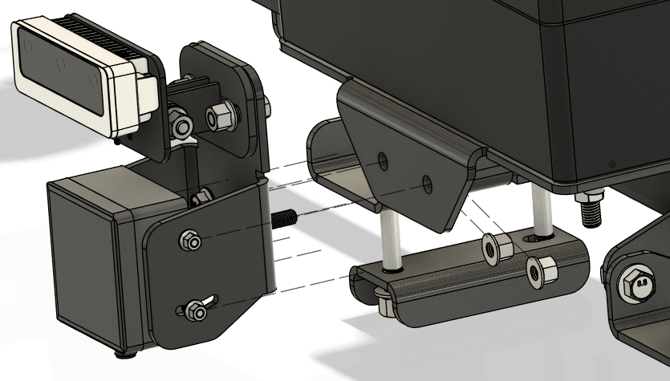
Step 2: Attach the front camera assembly to the radar bracket, reversing the direction of the M8 mounting bolts that held the camera.
Step 3: Attach the fully assembled radar mount with camera back to the ROPS bar assembly where you removed the front camera from.
Step 4: Adjust the radar’s angle to be 8.5 degrees down relative to the ground.
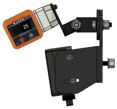
Step 5: Adjust the camera angle. For ROPS models, set the angle to 25 degrees down relative to the ground.
Step 6: Install the harness. Locate the unused harness branch labeled “IFM.” This may be coiled up on the ROPS bar assembly or run down the back side of the ROPS bar with the rest of the system’s cabling. The “IFM” branch is off of the harness that is labeled “BFE” and plugs into the black enclosure.

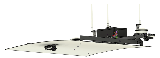
Fiberglass (OEM) Canopy Model Install
Before proceeding, ensure you have completed the steps in the "Hardware Installation" section.
Before installing radar on a canopy platform, please use a digital angle finder to level the top of the canopy with the ground. Failing to do so may result in poor radar performance.
Step 1: Locate and remove the camera from its mounting bracket by the two M8 bolts/nuts on the front side of the canopy
 |
 |
Step 2: Remove the mounting bracket from the canopy by removing the two bolts holding it to the canopy frame
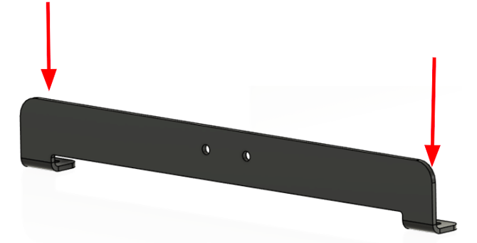
Step 3: Replace the bracket with the taller version provided
Step 4: Attach the radar mounting bracket with already installed radar
Step 5: Adjust the angle of the radar to 8.5 deg down relative to the ground using a digital angle finder
Step 6: Attach the front camera assembly to the radar mount

Step 7: Adjust the camera angle. For OEM canopy models, set the angle to 25 degrees down relative to the ground.
Step 8: Install the harness. Locate the unused harness branch labeled “IFM.” This may be coiled up on the ROPS bar assembly or run down the back side of the ROPS bar with the rest of the system’s cabling. The “IFM” branch is off of the harness that is labeled “BFE” and plugs into the black enclosure

Metal (Aftermarket) Canopy Model Install
Before proceeding, ensure you have completed the steps in the "Hardware Installation" section.
Before installing radar on a canopy platform, please use a digital angle finder to level the top of the canopy with the ground. Failing to do so may result in poor radar performance.
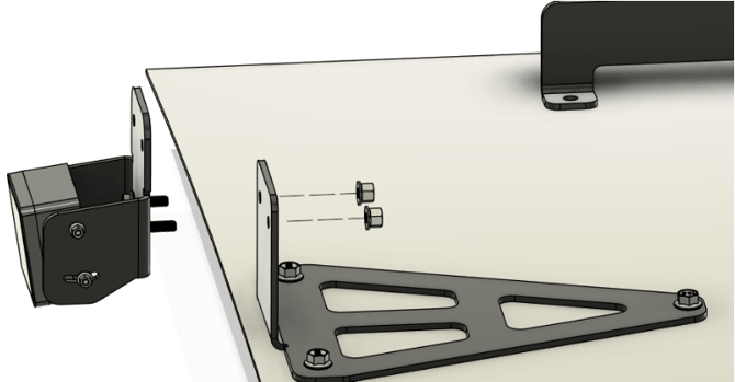
Step 1: Locate and remove the front camera assembly located towards the front of the canopy on the underside

Step 2: Remove the mounting bracket from the canopy from by removing the through bolt

Step 3: Place the new mounting bracket on the top of the canopy using the through bolt removed from the previous step to locate the bracket.
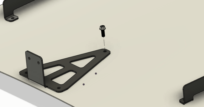
Step 4: Square the bracket up with the front edge of the canopy and mark the front two holes or use the bracket as a template to drill through holes in the canopy.

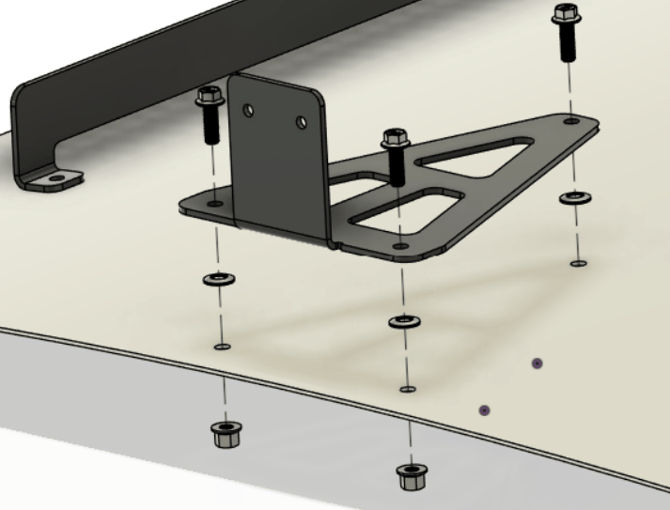
Step 5: After drilling the two 7/16” holes in the canopy, secure the bracket with the provided hardware. Make sure to place the sealed washers in between the bracket and canopy.
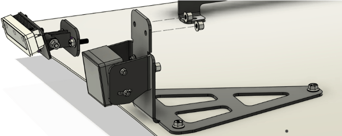
Step 6: With the bracket now secure, attach the radar mount to the base bracket.
Step 7: Adjust the angle of the radar to 8.5 deg down relative to the ground using a digital angle finder and tighten mounting screws.
Step 8: Attach the front camera assembly to the radar mounting bracket.
Step 9: Adjust the camera angle. For aftermarket canopy models, set the angle to 25 degrees down relative to the ground
Step 10: Install the harness. Locate the unused harness branch labeled “IFM.” This may be coiled up on the ROPS bar assembly or run down the back side of the ROPS bar with the rest of the system’s cabling. The “IFM” branch is off of the harness that is labeled “BFE” and plugs into the black enclosure. Reroute the camera cable to the top of the canopy and reconnect the front camera.

Software & Firmware Setup
Step 1: After hardware is installed, ensure the vPFM is updated to vOS 1.18.0 or newer. You can see the current SW version in the device page on vMC.

Step 2: Add the radar as a component to the equipment in vMC, and save the settings.
Step 3: Contact a Sabanto employee to enable Radar detection on vMC under the advanced tractor controls. Support mode is required to see this control.

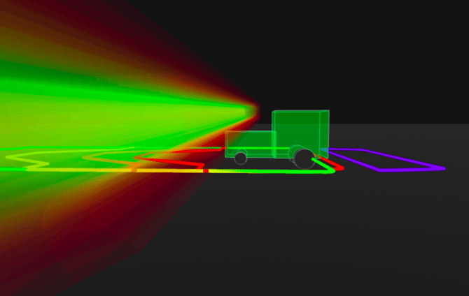
Theory of Operation
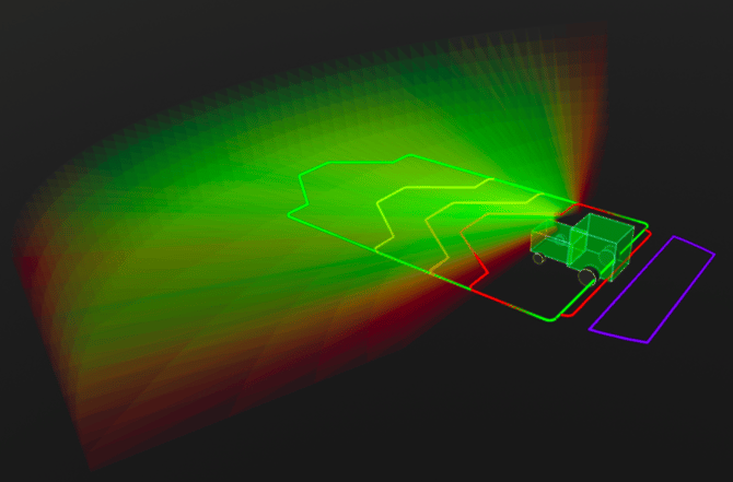
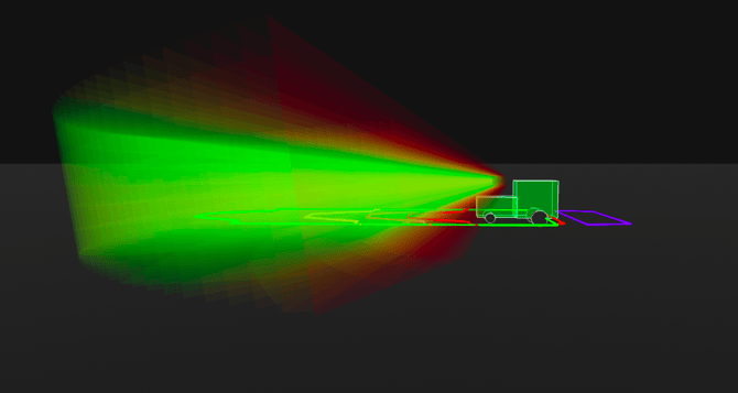
The radar detection system operates in two distinct parts: the radar sensor and the collision predictor. The radar system actively emits and receives radio waves in order to detect potential obstacles. Radar technology works well on metallic objects with well defined edges, like angle iron, and detections tend to be best when the sensor is moving relative to its environment. Once a potential obstacle is detected, the location is passed to the collision predictor inside of vOS.
Collision prediction is based on a few factors but the most important one is the speed of the vehicle. As speed increases, the predictor will “look” further ahead in order for the vehicle to stop before an actual collision. Because of this, there are a few non-intuitive scenarios that can occur with radar detections. Due to a limited FOV, and the speed affecting how far out the collision predictor is sensing obstacles, the maximum supported implement width decreases as speed decreases. This is due to the obstacles going outside of the radar’s FOV before the detection reaches the collision prediction zone. Once an obstacle enters a collision prediction zone, the tractor is commanded to stop as quickly as possible in order to prevent a collision.
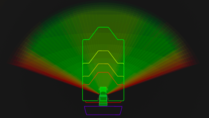
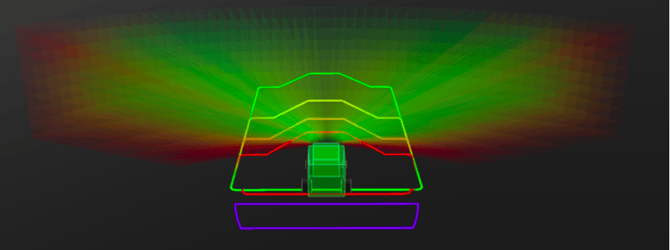
Zone Layout

Collision Zones
|
Speed (mph) |
Zone |
Effective Width (ft) |
Depth (ft) |
|
< 5 |
Red (minimum) |
15 |
15.4 |
|
5 - 7 |
Orange |
30-32 |
22 |
|
7 - 10 |
Yellow |
Unverified |
32 |
|
10+ |
Green |
Unverified |
50.4 |